Datasheet Summary
PG 24064-D
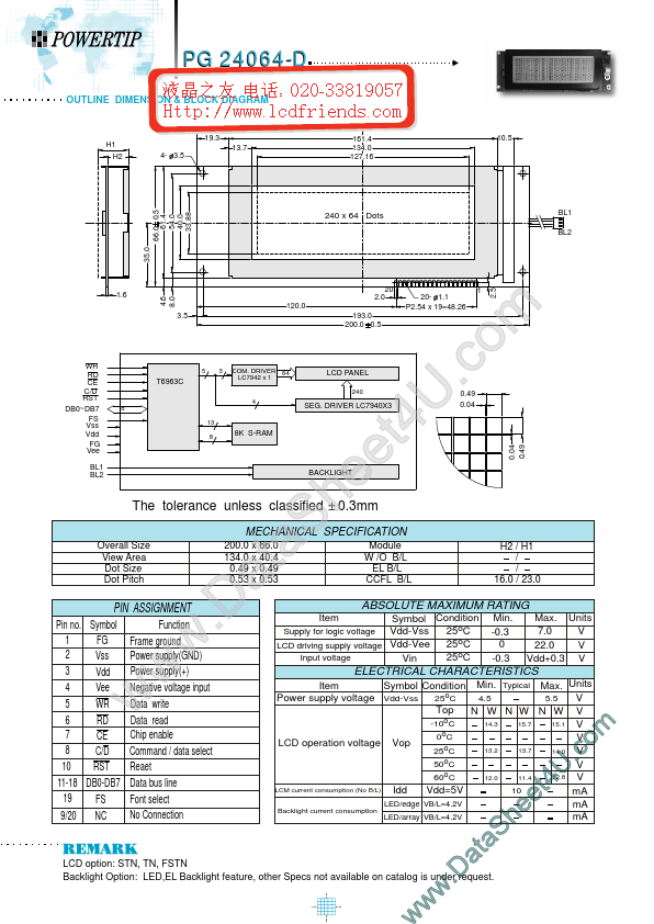
OUTLINE DIMENSION & BLOCK DIAGRAM
100.0 19.3 H1 H2 13.7 4- 3.5 161.4 134.0 127.16 10.5
66.0 0.5 61.4 54.0 40.0 33.88
240 x 64 Dots
BL1 BL2
4.6 8.0
20 2.0 120.0 3.5 193.0 200.0 0.5
20- 1.1 P2.54 x 19=48.26
BL1 BL2
BACKLIGHT
The tolerance unless classified
Overall Size View Area Dot Size Dot Pitch 200.0 x 66.0 134.0 x 40.4 0.49 x 0.49 0.53 x 0.53
MECHANICAL SPECIFICATION
PIN ASSIGNMENT
Pin no. Symbol FG 1 2 Vss 3 Vdd 4 Vee 5 WR RD 6 7 CE 8 C/D 10 RST 11-18 DB0-DB7 19 FS NC 9/20 Function Frame ground Power supply(GND) Power supply(+) Negative voltage input Data write Data read Chip enable mand / data select Reaet Data bus line Font select No Connection w...