XP6534
Key Features
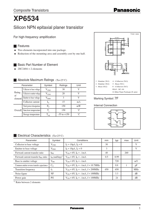
- 65 1 2 3 6 5 4
- 9±0.1 q 2SC2404 × 2 elements
- 7±0.1 0 to 0.1
- 2±0.1 s Absolute Maximum Ratings Parameter Collector to base voltage Rating Collector to emitter voltage of element Emitter to base voltage Collector current Total power dissipation Overall Junction temperature Storage temperature Symbol VCBO VCEO VEBO IC PT Tj Tstg (Ta=25˚C) Ratings 30 20 3 15 150 150 -55 to +150 Unit V V V mA mW ˚C 1 : Emitter (Tr1) 2 : Emitter (Tr2) 3 : Base (Tr2) 4 : Collector (Tr2) 5 : Base (Tr1) 6 : Collector (Tr1) EIAJ : SC-88 S-Mini Type Package (6-pin) Marking Symbol: 7F Internal Connection 1 Tr1 6 5 4 ˚C 2 3 Tr2 s Electrical Characteristics Parameter Collector to base voltage Emitter to base voltage Forward current transfer ratio Forward current transfer hFE ratio Base to emitter voltage Common emitter reverse transfer capacitance Transition frequency Noise figure Power gain
- 1 (Ta=25˚C) Symbol VCBO VEBO hFE hFE (small/large)*1 VBE Cre fT NF PG Conditions IC = 10µA, IE = 0 IE = 10µA, IC = 0 VCB = 6V, IE = -1mA VCB = 6V, IE = -1mA VCB = 6V, IE = -1mA VCB = 6V, IE = -1mA, f = 10.7MHz VCB = 6V, IE = -1mA, f = 200MHz VCB = 6V, IE = -1mA, f = 100MHz VCB = 6V, IE = -1mA, f = 100MHz 450 min 30 3 40 0.5 0.99 720 0.8 650 3.3 24 1 mV pF MHz dB dB 260 typ max Unit V V Ratio between 2 elements
- 12 -0.02 s Basic Part Number of Element
- 2 +0.05 1 Composite Transistors PT - Ta 250 XP6534 IC - VCE 12 Ta=25˚C IB=100µA 12 VCE=6V Ta=25˚C 10 IC - I B Total power dissipation PT (mW) Collector current IC (mA) 8 80µA 60µA Collector current IC (mA) 200 10 8 150 6 40µA 6 100 4 4 50 2 20µA 2