EEETG1V101P
Key Features
- Specifications Category Temp. Range Rated W.V. Range Nominal Cap. Range Capacitance Tolerance DC Leakage Current tan δ Characteristics at Low Temperature W.V. (V) Z(-25 °C)/Z(+20 °C) Z(-40 °C)/Z(+20 °C) 10 3 6 -40 °C to +125 °C 10 to 100 10 µF to 4700 µF ±20 % (120 Hz/+20 °C) I < 0.01 CV After 2 minutes Please see the attached standard products list 16 25 35 50 63 80 100 2 2 2 2 2 2 2 4 4 3 3 3 3 3 (Impedance ratio at 120 Hz) After applying rated working voltage for 1000 hours (φ8҂6.2), 2000 hours (φ8҂ 10.2 <) at +125 °C±2 °C and then being stabilized at +20 °C, capacitors shall meet the following limits. Endurance Capacitance change tan δ DC leakage current ±30 % of initial measured value (code U : ±35 %) < 300 % of initial specified value (code U : ±350 %) < initial specified value Shelf Life After storage for 1000 hours at +125 °C±2 °C with no voltage applied and then being stabilized at +20 °C, capacitors shall meet the limits specified in Endurance (With voltage treatment) After reflow soldering and then being stabilized at +20 °C, capacitors shall meet the following limits. Capacitance change ±10 % of initial measured value tan δ < initial specified value DC leakage current < initial specified value Resistance to Soldering Heat
- Frequency correction factor for ripple current Frequency (Hz) Correction factor 120 0.65 1k 0.85 10 k 0.95 100 k to 1.00
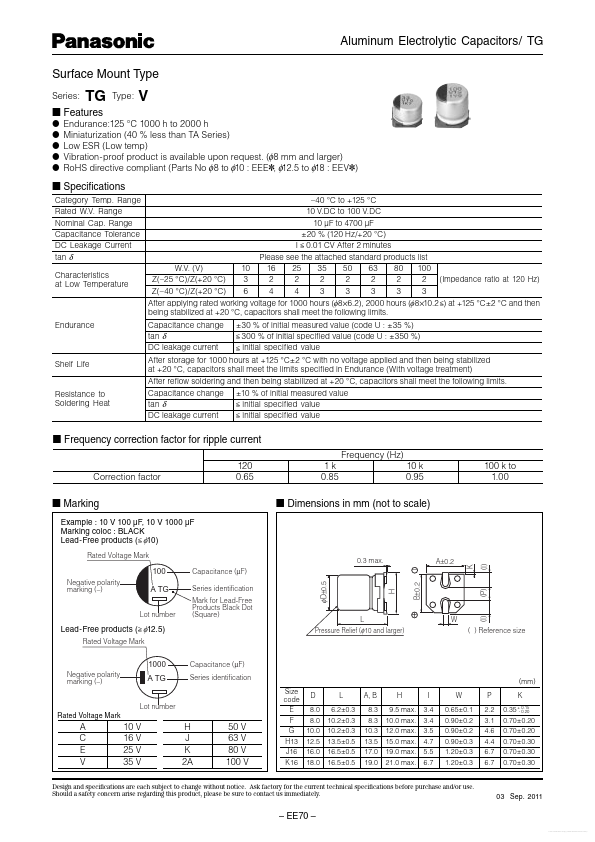
- Marking Example : 10 V 100 µF, 10 V 1000 µF Marking coloc : BLACK Lead-Free products ( < φ10) Rated Voltage Mark
- Dimensions in mm (not to scale) 100 Negative polarity marking (-)