Panasonic GN01094B
GaAs MMIC
| Part No. | GN01094B |
|---|---|
| Datasheet | GN01094B Download |
| Manufacturer |  Panasonic |
| Description | GaAs MMIC |
| Buy | Stock & Price |
ELECTRICAL CHARACTERISTICS
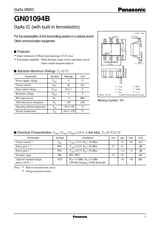
VDD1=VDD2=VREF=3.0 V, f=906 MHz, Ta=25 °C±3 °C Parameter Circuit current *1 Symbol IDD PG1 PG2 DR ACP Conditions VAGC=2.0 V, PIN=−20 dBm VAGC=2.0 V, PIN=−20 dBm VAGC=0.5 V, PIN=−20 dBm PG1−PG2 PIN=−15 dBm, POUT=5 dBm ±900 kHz Detuning, 30 kHz Bandwidth min typ 32 0.7±0.1 0.9±0.1 sABSOLUTE MAXIMUM RATINGS
Ta=25 °C max 40 −8 −49 Unit mA dB dB dB dBc Power gain 1 *1 Power gain 2 *1 27 31 −14 Dynamic range Adjacent channel leakage power (ACP) *1, 2 Note) *1 : Refer to measurement circuit. *2 : Design-guaranteed items. 35 45 −54 0.2±0.1 sFEATURES
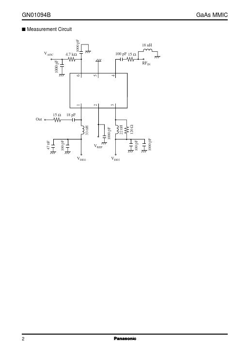
2.1±0.1 0.1 For the preamplifier of the transmitting section in a cellular phone Other communication equipment 0.2±0.05 0.12 +0.05 −0.02 4 6 5 1 GN01094B s Measurement Circuit 1000 pF GaAs MMIC 18 nH 100 pF 15 Ω RFIN VAGC 4.7 kΩ 1000 pF 5 6 1 15 Ω Out 18 pF 2 3 4 33 nH 1000 pF 22 nH 120 Ω VREF VDD2 VDD1 2 1000 pF 100 pF 100 pF 47 nF