PI74SSTU32864A
PI74SSTU32864A is 25-Bit 1:1 or 14-Bit 1:2 Configurable Registered manufactured by Pericom Semiconductor.
Features
- PI74SSTU32864A is designed for low-voltage operation, VDD = 1.8V
- Supports Low Power Standby Operation
- Enhanced Signal Integrity for 1 and 2 Rank Modules
- All Inputs are SSTL_18 patible, except RST, C0, C1, .. which are LVCMOS.
- Output drivers are optimized to drive DDR2 DIMM loads
- Designed for DDR2 Memory
- Packaging (Pb-free & Green available): -96 Ball LFBGA (NB)
Description
Peri Semiconductor’s PI74SSTU32864A logic circuit is produced using advanced CMOS technology. This 25-Bit 1:1 or 14-Bit 1:2 configurable registered buffer is designed for 1.7V to 1.9V VDD operation. All clock and data inputs are patible with the JEDEC standard for SSTL_18. The control inputs are LVCMOS. All outputs are 1.8V LVCMOS drivers that have been optimized to drive the DDR2 DIMM load. The SSTU32864A operates from a differential clock (CK and CK). Data is registered at the crossing of CK going high, and CK going low. The C0 input controls the pinout configuration of the 1:2 pinout from A configuration (when LOW) to B configuration (when HIGH). The C1 input controls the pinout configuration for 25-Bit 1:1 (when LOW) to 14-Bit 1:2 (when HIGH). The device supports low-power standby operation. When the reset input (RST) is low, the differential input receivers are disabled and undriven (floating) data, clock and reference voltage (VREF) inputs are allowed. In addition , when RST is low, all registers are reset, and all outputs are forced low. The LVCMOS RST and Cn inputs must always be held at a valid logic high or low level.
1D C1 R
QCKEB-
QODTA
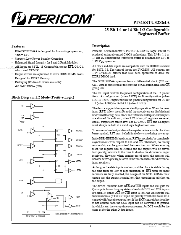
Block Diagram 1:2 Mode (Positive Logic)
CK CK
VREF
DCKE
QCKEA
To ensure defined outputs from the register before a stable clock has been supplied, RST must be held in the low state during power up. In the DDR-II RDIMM application, RST is specified to be pletely asynchronous with respect to CK and CK. Therefore, no timing relationship can be guaranteed between the two. When entering reset, the register will be cleared...