PhaseLink PLL205-11
The signal provided to this input pin is buffered to 13 SDRAM outputs.| Part No. | PLL205-11 |
|---|---|
| Datasheet | PLL205-11 Download |
| Manufacturer |  PhaseLink |
| Description | Motherboard Clock Generator |
| Buy | Stock & Price |
FEATURES
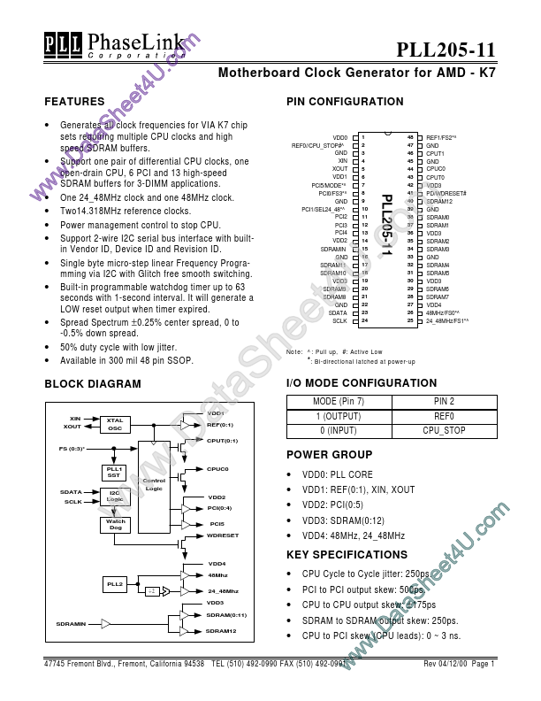
PIN CONFIGURATION e h● Generates all clock frequencies for VIA K7 chip S sets requiring ta multiple CPU clocks and high speed a SDRAM buffers.
● Support pair of differential CPU clocks, one .D oneCPU, open-drain 6 PCI and 13 high-speed w SDRAM buffers for 3-DIMM applications. w w● One 24_48MHz clock and one 48MHz clock.
●
●
●
●
●
●
●
● Two14.318MHz reference clocks. Power management control to stop CPU. Support 2-wire I2C serial bus interface with builtin Vendor ID, Device ID and Revision ID. Single byte micro-step linear Frequency Programming via I2C with Glitch free smooth switching. Built-in programmable watchdog timer up to 63 seconds with 1-second interval. It will generate a LOW reset output when timer expired. Spread Spectrum ± 0.25% center spread, 0 to -0.5% down spread. 50% duty cycle with low jitter. Available in 300 mil 48 pin SSOP. BLOCK DIAGRAM XIN XOUT XTAL OSC FS (0:3)* PLL1 SST SDATA SCLK I2C Logic Watch Dog m o .c U 4 t e e h S a t a .D w w w 8 9 41 40 39 38...

