Philips 74HCT109
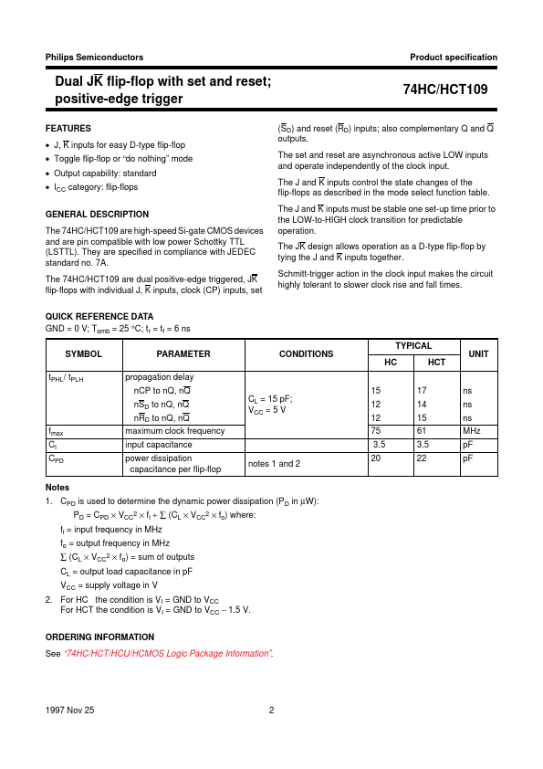
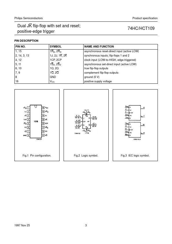
The 74HC/HCT109 are high-speed Si-gate CMOS devices and are pin compatible with low power Schottky TTL (LSTTL). They are specified in compliance with JEDEC standard no. The 74HC/HCT109 are dual positive-edge triggered, JK flip-flops with individual J, K inputs, clock (CP) inputs, set QUICK REFERENCE DATA GND = 0 V; Tamb = 25 °C; tr = tf = 6 ns 74HC/HCT109 (SD) and reset (RD) inputs; also complementary Q and Q outputs.| Part No. | 74HCT109 |
|---|---|
| Datasheet | 74HCT109 Download |
| Manufacturer |  Philips |
| Description | Dual JK flip-flop |
| Buy | Stock & Price |
FEATURES
● J, K inputs for easy D-type flip-flop● Toggle flip-flop or “do nothing” mode
● Output capability: standard
● ICC category: flip-flops
GENERAL DESCRIPTION
7A. The set and reset are asynchronous active LOW inputs and operate independently of the clock input. The J and K inputs control the state changes of the flip-flops as described in the mode select function table. The J and K inputs must be stable one set-up time prior to the LOW-to-HIGH clock transition for predictable operation. The JK design allows operation as a D-type flip-flop by tying the J and K inputs together. Schmitt-trigger action in the clock input makes the circuit highly tolerant to slower clock rise and fall times. TYPICAL SYMBOL tPHL/ tPLH PARAMETER propagation delay nCP to nQ, nQ nSD to nQ, nQ nRD to nQ, nQ fmax CI CPD Notes 1. CPD is used to determine the dynamic power dissipation (PD in µW): PD = CPD × VCC2 × fi + ∑ (CL × VCC2 × fo) where: fi = input frequency in MHz fo = output frequency in MHz ∑ (CL × VCC2 × fo) = sum of outputs CL = output load capacitance in pF VCC = supply voltage in V 2.