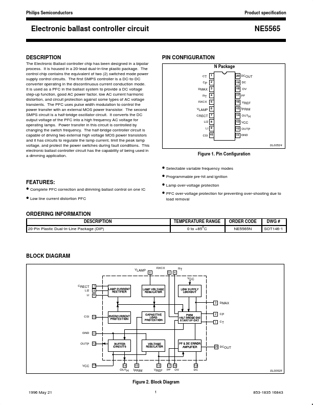
DESCRIPTION
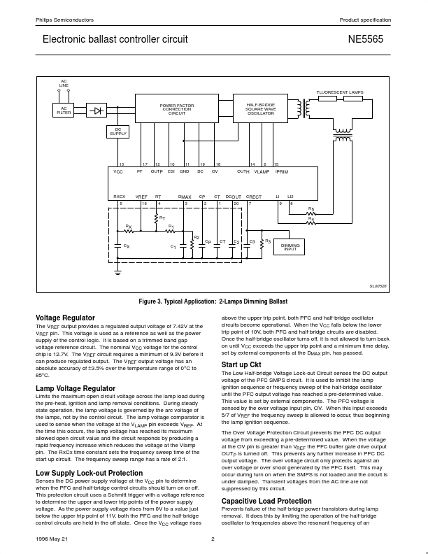
The control chip contains the equivalent of two (2) switched mode power supply control circuits. The first SMPS controller is a DC-to-DC converter operating in the discontinuous current conduction mode. It is used as a PFC in the ballast system to provide a DC voltage step-up function, good AC power factor, low AC current harmonic distortion, and circuit protection against some types of AC voltage transients. The PFC uses pulse width modulation to control the power transfer with an external MOS power transistor. The second SMPS circuit is a half-bridge oscillator circuit. It converts the DC output voltage of the PFC into a high frequency AC voltage for operating lamps. Power transfer in this circuit is controlled by changing the switch frequency. The half-bridge controller circuit is capable of driving two external high voltage MOS power transistors and it has circuits to regulate the lamp current, limit the peak lamp voltage, and protect the power switches during fault conditions. Philips