Philips SAA7117
The result of the automatic color standard detection can be read via I2C • I2C read back of digital AGC gain factor • Blue screen output in case of absent input signals • RMS Noise level estimation possible • Lead-free BGA156 package available 1.2 SAA7117A • Sixteen analog input pins, allowing for multiple combinations of composite, S-Video and component video; • Eight 3-level capable sensor pins for D-connector or SCART AV- and RGB- switch signals (three of those can be active simultaneously); one Fast Blanking input • Four studio-quality 10-bit CMOS Analog-to-Digital Converters (ADC) at...| Part No. | SAA7117 |
|---|---|
| Datasheet | SAA7117 Download |
| Manufacturer |  Philips |
| Description | Multistandard video decoder |
| Buy | Stock & Price |
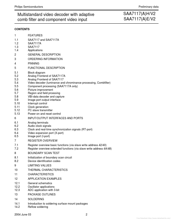
FEATURES
SAA7117 and SAA7117A SAA7117A SAA7117APPLICATIONS
GENERAL DESCRIPTION
ORDERING INFORMATION PINNING FUNCTIONALDESCRIPTION
Block diagram Analog Frontend of SAA7117A Analog Frontend of SAA7117 Video decoder (luminance and chrominance processing, Combfilter) Component processing (SAA7117A only) Picture improvement Region and field prcessing VBI-data decoder and capture Image port output interface Interrupt control Clock generation I2C slave transmitter Power-on and reset control INPUT/OUTPUT INTERFACES AND PORTS Analog terminals Audio clock signals Clock and real-time synchronization signals (RT-port) Video expansion port (X-port) Image port (I-port) REGISTER OVERVIEW Register overview basic functions (via slave write address 42/40) Register overview extended functions (via slave write address 4A/48) BOUNDARY SCAN TEST Initialization of boundary scan circuit Device identification codes LIMITING VALUES THERMAL CHARACTERISTICS CHARACTERISTICS APPLICATION EXAMPLES General schematic...