• Part: PT6464
  • Description: 14-A 5-V Input Adjustable Integrated Switching Regulator
  • Category: Voltage Regulator
  • Manufacturer: Power Trend
  • Size: 199.37 KB
Download PT6464 Datasheet PDF
Power Trend
PT6464
PT6464 is 14-A 5-V Input Adjustable Integrated Switching Regulator manufactured by Power Trend.
- Part of the PT6460 comparator family.
Features - 5 V Input - 14 A Output Current - Low-Profile (8mm) - DSP patible - >90 % Efficiency - Adjustable Output Voltage - On/Off Inhibit - Pre-Bias Start-up Capability - Over-Current Protection - Output Remote Sense - Optional Output Capacitor - Small Footprint (0.64 in², Suffix ‘N’) - Surface Mount patible - IPC Lead Free 2 Description 
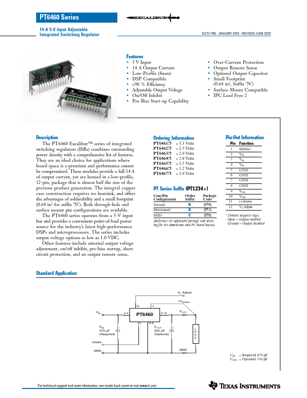
The PT6460 Excalibur™ series of integrated switching regulators (ISRs) bines outstanding power density with a prehensive list of features . They are an ideal choice for applications where board space is a premium and performance cannot be promised. These modules provide a full 14 A of output current, yet are housed in a low-profile, 12-pin, package that is almost half the size of the previous product generation. The integral copper case construction requires no heatsink, and offers the advantages of solderability and a small footprint (0.64 in² for suffix ‘N’). Both through-hole and surface mount pin configurations are available. The PT6460 series operates from a 5-V input bus and provides a convenient point-of-load power source for the industry’s latest high-performance DSPs and microprocessors. The series includes output voltage options as low as 1.0 VDC. Other features include external output voltage adjustment, on/off inhibit, pre-bias startup, short circuit protection, and an output remote sense. Ordering Information PT6461H = 3.3 Volts PT6462H = 2.5 Volts PT6463H = 2.0 Volts PT6464H = 1.8 Volts PT6465H = 1.5 Volts PT6466H = 1.2 Volts PT6467H = 1.0 Volts PT Series Suffix (PT1234 x ) Case/Pin Configuration Order Suffix Package Code Vertical Horizontal N (EPH) A (EPJ) C (EPK) (Reference the applicable package code drawing for the dimensions and PC board layout) Pin-Out Information Pin Function 1 Inhibit- 2 Vin 3 Vin 4 Vin 5 GND 6 GND 7 GND 8 GND 9 Vout 10 Vout 11 (+)Sense 12 Vo Adjust - Denotes negative logic: Open = Output enabled Ground = Output disabled Standard Application CIN 470 µF (Required)...