PSKD56 Overview
Key Features
| Part | PSKD56 |
|---|---|
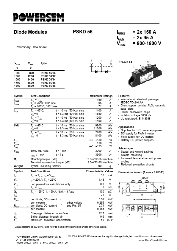
| Description | Diode Module |
| Category | Diode |
| Manufacturer | Powersem |
| Size | 203.47 KB |
| Seller | Inventory | Price Breaks | Buy |
|---|---|---|---|
| TME | 0 | 1+ : 33.85 USD 3+ : 29.96 USD 6+ : 26.89 USD |
View Offer |
| TME | 0 | 1+ : 33.85 EUR 3+ : 29.96 EUR 6+ : 26.89 EUR |
View Offer |
| Part Number | Manufacturer | Description |
|---|---|---|
| HFDOM44P-xxxSx | Hanbit Electronics | 44Pin Flash Disk Module |
| HFDOM40B-xxxSx | Hanbit Electronics | 40Pin Flash Disk Module |
| HFDOM40P-xxxSx | Hanbit Electronics | 40Pin Flash Disk Module |