PC4004-A Overview
Key Features
- other Specs not available on catalog is under request
| Part | PC4004-A |
|---|---|
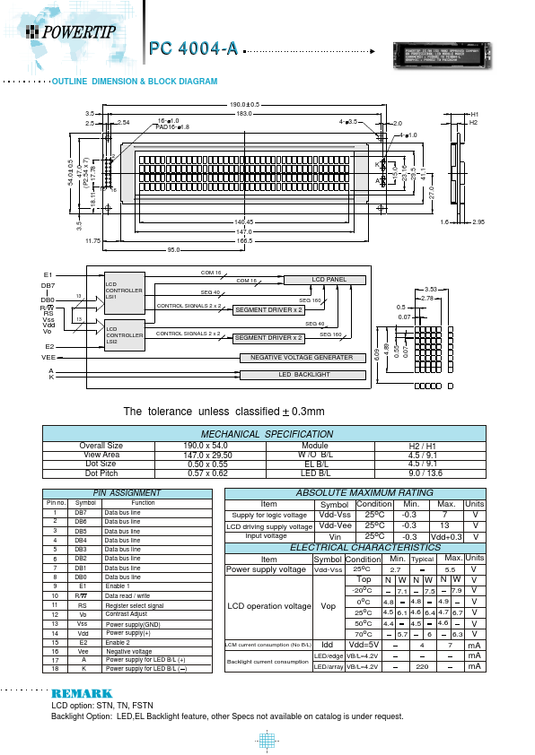
| Description | OUTLINE DIMENSION & BLOCK DIAGRAM |
| Manufacturer | Powertip Technology |
| Size | 76.49 KB |
| Part Number | Manufacturer | Description |
|---|---|---|
| pc4004d | POWERTIP | LCD_Module |
| PC4004LRU-ASO_E_SA | POWERTIP | LCD_Module |
| pc4004a | POWERTIP | LCD_Module |
| pc4004l | POWERTIP | LCD_Module |
| PC400 | Sharp Corporation | Compact/ Surface Mount Type OPIC Photocoupler |