Datasheet Summary
..
Radio Clock Receiver Antenna SMD
C/Severo Ochoa 33
- Parque Tecnológico de Andalucía. 29590 Campanillas. Málaga (Spain) Phone +34 951 231 320 Fax +34 951 231 321 E-mail: info@grupopremo. Web http://.grupopremo.
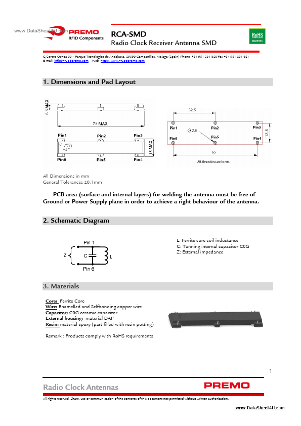
1. Dimensions and Pad Layout
All Dimensions in mm General Tolerances ±0.1mm
PCB area (surface and internal layers) for welding the antenna must be free of Ground or Power Supply plane in order to achieve a right behaviour of the antenna.
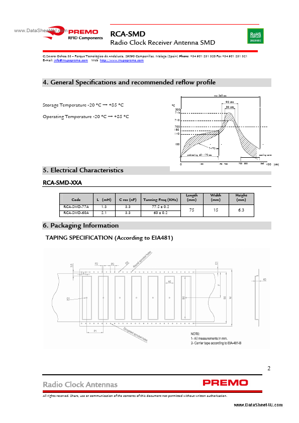
2. Schematic Diagram
L: Ferrite core coil inductance C: Tunning internal capacitor C0G Z: External impedance
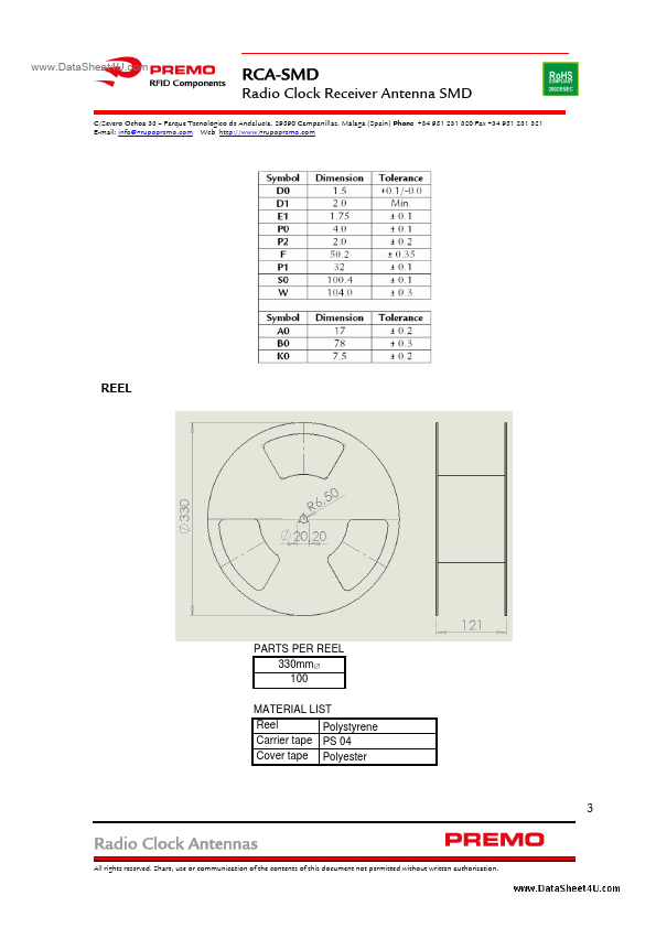
3. Materials
Core: Ferrite Core Wire: Enamelled and Selfbonding copper wire Capacitor: C0G...