RS201L Overview
Key Specifications
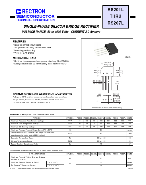
Height: 14.4 mm
Length: 18 mm
Width: 6.6 mm
Max Operating Temp: 150 °C
| Part | RS201L |
|---|---|
| Description | SINGLE-PHASE SILICON BRIDGE RECTIFIER |
| Manufacturer | Rectron |
| Size | 22.52 KB |
Height: 14.4 mm
Length: 18 mm
Width: 6.6 mm
Max Operating Temp: 150 °C
| Seller | Inventory | Price Breaks | Buy |
|---|---|---|---|
| Worldway Electronics | 18147 | 7+ : 0.1232 USD 10+ : 0.1207 USD 100+ : 0.117 USD 500+ : 0.1133 USD |
View Offer |
| Quest | 553 | 1+ : 0.66 USD 9+ : 0.55 USD 37+ : 0.44 USD 137+ : 0.308 USD |
View Offer |
| Part Number | Manufacturer | Description |
|---|---|---|
| RS201L | Galaxy | SILICON BRIDGE RECTIFIERS |
| RS201 | Rectron | SILICON BRIDGE RECTIFIER |
| RS201 | MIC | SINGLE PHASE BRIDGE RECTIFIER |
| RS201 | SeCoS Halbleitertechnologie GmbH | 2.0AMP Single Phase Bridge Rectifiers |
| RS201 | Mospec Semiconductor | SINGLE-PHASE BRIDGE RECTIFIER |