Datasheet Summary
Digitally Controlled Potentiometer (XDCP™), Terminal Voltage 0V to 13.2V, 128 Taps Up/Down Interface
FN8083 Rev 1.00 August 27, 2015
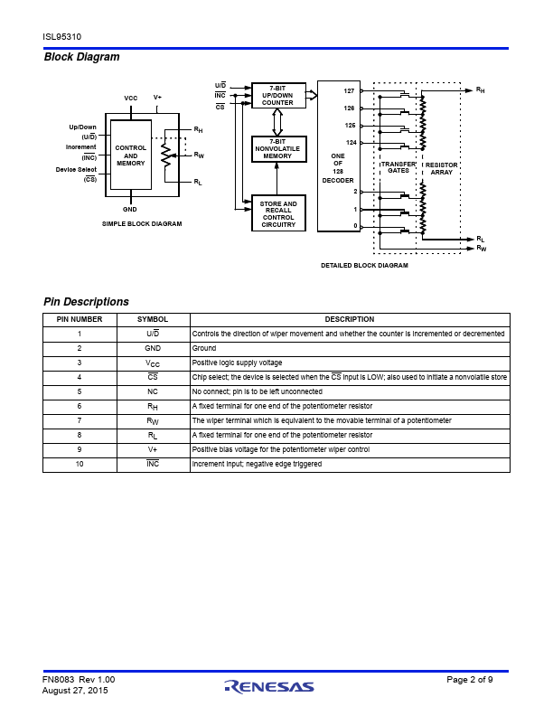
The Intersil ISL95310 is a digitally controlled potentiometer (XDCP). The device consists of a resistor array, wiper switches, a control section, and nonvolatile memory. The wiper position is controlled by an Up/Down interface.
The potentiometer is implemented by a resistor array posed of 127 resistive elements and a wiper switching network. Between each element and at either end are tap points accessible to the wiper terminal. The wiper of each potentiometer has an associated volatile Wiper Counter Register (WR) and a non-volatile...