Datasheet4U Logo Datasheet4U.com

X9C104P - Digitally Controlled Potentiometer

This page provides the datasheet information for the X9C104P, a member of the X9C102 Digitally Controlled Potentiometer family.

Datasheet Summary

Description

INCREMENT The INC input is negative-edge triggered.

Toggling INC will move the wiper and either increment or decrement the counter in the direction indicated by the logic level on the U/D input.

Features

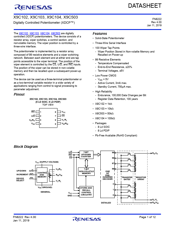
  • Solid-State Potentiometer.
  • Three-Wire Serial Interface.
  • 100 Wiper Tap Points - Wiper Position Stored in Non-volatile Memory and Recalled on Power-up.
  • 99 Resistive Elements - Temperature Compensated - End-to-End Resistance, ±20% - Terminal Voltages, ±5V.
  • Low Power CMOS - VCC = 5V - Active Current, 3mA max. - Standby Current, 750µA max.
  • High Reliability - Endurance, 100,000 Data Changes per Bit - Register Data Retention, 100 years.
  • X.

📥 Download Datasheet

Datasheet preview – X9C104P

Datasheet Details

Part number X9C104P
Manufacturer Renesas
File Size 614.88 KB
Description Digitally Controlled Potentiometer
Datasheet download datasheet X9C104P Datasheet
Additional preview pages of the X9C104P datasheet.
Other Datasheets by Renesas

Full PDF Text Transcription

Click to expand full text
DATASHEET X9C102, X9C103, X9C104, X9C503 Digitally Controlled Potentiometer (XDCP™) The X9C102, X9C103, X9C104, X9C503 are digitally controlled (XDCP) potentiometers. The device consists of a resistor array, wiper switches, a control section, and nonvolatile memory. The wiper position is controlled by a three-wire interface. The potentiometer is implemented by a resistor array composed of 99 resistive elements and a wiper switching network. Between each element and at either end are tap points accessible to the wiper terminal. The position of the wiper element is controlled by the CS, U/D, and INC inputs. The position of the wiper can be stored in non-volatile memory and then be recalled upon a subsequent power-up operation.
Published: |