L-819 Overview
Key Specifications
Pins: 3
Height: 13.5 mm
Max Operating Temp: 85 °C
Min Operating Temp: -40 °C
Key Features
- Fax: (714) 896-0971
| Part | L-819 |
|---|---|
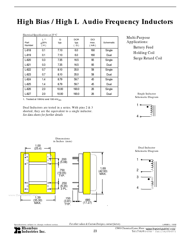
| Description | High Bias / High L Audio Frequency Inductors |
| Manufacturer | Rhombus Industries |
| Size | 41.77 KB |
Pins: 3
Height: 13.5 mm
Max Operating Temp: 85 °C
Min Operating Temp: -40 °C
| Seller | Inventory | Price Breaks | Buy |
|---|---|---|---|
| Newark | 432 | 1+ : 0.692 USD 10+ : 0.562 USD 100+ : 0.396 USD 600+ : 0.349 USD |
View Offer |
| Farnell | 432 | 1+ : 0.449 GBP 10+ : 0.44 GBP 25+ : 0.431 GBP 50+ : 0.422 GBP |
View Offer |
| Part Number | Manufacturer | Description |
|---|---|---|
| L-819EGW | Kingbright | 10mm ROUND LED LAMP |
| L-813SRC-E | Kingbright | 10mm SUPER BRIGHT BIG LAMPS |
| L-813SRD-D | Kingbright | 10mm SUPER BRIGHT BIG LAMPS |
| L-813SRD-E | Kingbright | 10mm SUPER BRIGHT BIG LAMPS |
| L-813SRC-C | Kingbright | 10mm SUPER BRIGHT BIG LAMPS |