BD3491FS
BD3491FS is Sound Processor manufactured by ROHM.
Description
Built in stereo 6 input selectors and volume that there is not an impedance change of a volume terminal. And this is sound processor can realize 2-band equalizer (Bass/Treble, Gain±14d B / 2d B_step) and Bass Boost, Output gain, Surround by external ponents.
Features
Equipped with 6 single ended stereo input selectors Built-in input gain controller suitable for mobile audio. Volume input terminal can be used as a microphone input terminal since its impedance remains constant even if volume setting is changed. Bi-CMOS process is suitable for the design of low current and low energy. It also provides more quality for Bi-CMOS small scale regulator and heat in a set. The package of this IC is SSOP-A32. Sound input terminals and output terminals arrangement is optimized for easy and fast layout of PCB pattern. At the same time, it minimizes PCB area.
Applications Suitable for mini-ponents or micro ponents. Used for audio equipment of TV, DVD, etc.
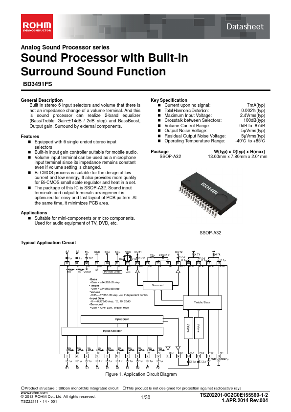
Typical Application Circuit
Key Specification Current upon no signal: Total Harmonic Distortion: Maximum Input Voltage: Crosstalk between Selectors: Volume Control Range: Output Noise Voltage: Residual Output Noise Voltage:
Operating Temperature Range:
7m A(typ) 0.002%(typ) 2.4Vrms(typ) 100d B(typ)
0d B to -87d B 5µVrms(typ) 5µVrms(typ) -40℃ to +85℃
Package SSOP-A32
W(typ) x D(typ) x H(max) 13.60mm x 7.80mm x 2.01mm
SSOP-A32
Figure 1. Application Circuit Diagram
○Product structure:Silicon monolithic integrated circuit ○This product is not designed for protection against radioactive rays
..rohm. © 2013 ROHM Co., Ltd. All rights reserved.
TSZ22111- 14- 001
1/30
TSZ02201-0C2C0E155560-1-2 1.APR.2014 Rev.004
Pin Configuration
B1 1 B2 2 C1 3 C2 4 D1 5 D2 6 E1 7 E2 8 F1 9 F2 10 SEL2 11 SEL1 12 VOL1 13 VOL2 14 TC2 15 TC1 16
32 A1 31 A2 30 FIL 29 GND 28 SDA 27 SCL 26 VCC 25 OUT1 24 SB1 23 SR 22 SB2 21 OUT2 20 BCB1 19 BCA1 18 BCA2 17 BCB2
Figure 2. Pin Configuration
Pin Descriptions
Terminal...