BU2114 Overview
Key Features
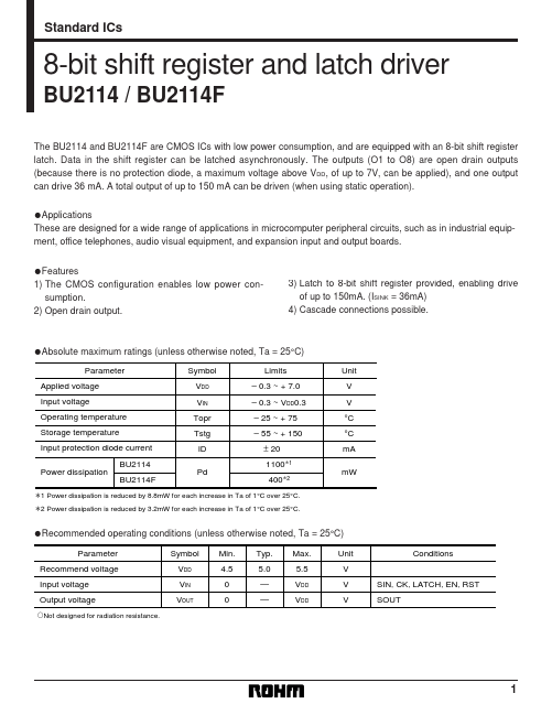
- The CMOS configuration enables low power consumption
- Open drain output
- Latch to 8-bit shift register provided, enabling drive of up to 150mA. (ISINK = 36mA)
- Cascade connections possible
| Part | BU2114 |
|---|---|
| Description | 8-bit shift register and latch driver |
| Manufacturer | ROHM |
| Size | 115.75 KB |
| Part Number | Manufacturer | Description |
|---|---|---|
| BU211 | Inchange Semiconductor | NPN Transistor |