Datasheet4U Logo Datasheet4U.com

SS41FLSOT - Hall Latch Position Sensor

Download the SS41FLSOT datasheet PDF. This datasheet also covers the SS41F variant, as both devices belong to the same hall latch position sensor family and are provided as variant models within a single manufacturer datasheet.

General Description

The SS41F is an integrated Hall effect latched sensor designed for electronic commutation of brush-less DC motor applications.

Key Features

  • 4.5V to 24V Operation.
  • -40°C to 150°C Superior temperature operation.
  • Bipolar technology.
  • Open-collector 25 mA output.
  • Reverse battery protection.
  • Small Size-SOT23 3L or SIP 3L.
  • Solid-state reliability.
  • Resistant to physical stress.
  • Activate with small, commercially available permanent magnets SS41F Hall Latch Position Sensor.

📥 Download Datasheet

Note: The manufacturer provides a single datasheet file (SS41F-SEC.pdf) that lists specifications for multiple related part numbers.

Datasheet Details

Part number SS41FLSOT
Manufacturer SEC
File Size 196.43 KB
Description Hall Latch Position Sensor
Datasheet download datasheet SS41FLSOT Datasheet

Full PDF Text Transcription (Reference)

The following content is an automatically extracted verbatim text from the original manufacturer datasheet and is provided for reference purposes only.

View original datasheet text
Features and Benefits – 4.5V to 24V Operation – -40°C to 150°C Superior temperature operation – Bipolar technology – Open-collector 25 mA output – Reverse battery protection – Small Size-SOT23 3L or SIP 3L – Solid-state reliability – Resistant to physical stress – Activate with small, commercially available permanent magnets SS41F Hall Latch Position Sensor Application Examples – Brushless DC motor commutation – Automotive, Consumer and Industrial – Solid-state switch – Speed measurement – Revolution counting – Angular position detection – Proximity detection 3 pin SOT23 (suffix SO) 3 pin SIP (suffix UA) 
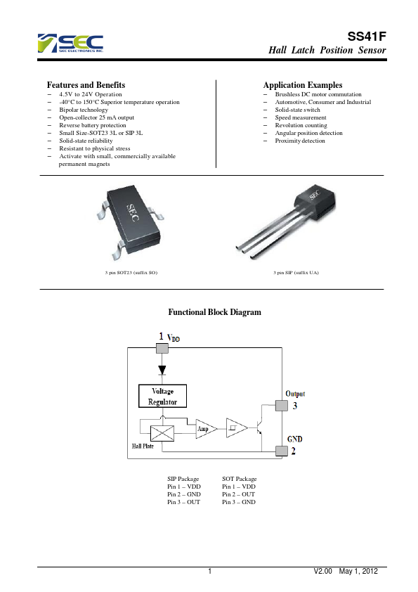
Functional Block Diagram SIP Package Pin 1 – VDD Pin 2 – GND Pin 3 – OUT SOT Package Pin 1 – VDD Pin 2 – OUT Pin 3 – GND 1 V2.