DESCRIPTION
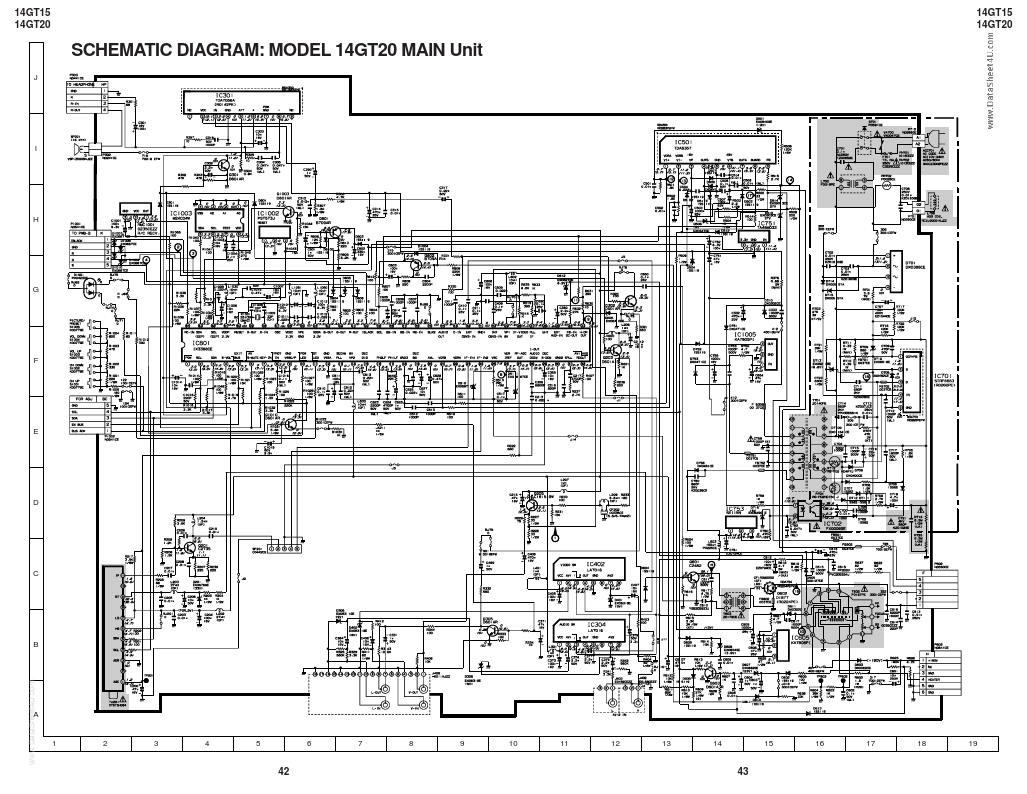
OF SCHEMATIC DIAGRAM . 35 SCHEMATIC DIAGRAM s INFRARED REMOTE CONTROL UNIT .. 36 s TUNER .....................................................37 s 14GT15, 14GT20 HOTEL MODE APPLICATION ..........................................38 Page s HEAD PHONE Unit and CRT Socket Unit ...................................... 39 s MAIN Unit ................................................. 40 » BLOCK DIAGRAM .........................................44 » PRINTED WIRING BOARD ASSEMBLIES .. 49 » REPLACEMENT PARTS LIST s ELECTRICAL PARTS .............................. 54 s MISCELLANEOUS PARTS ...................... 58 s SUPPLIED ACCESSORIES .................... 58 s PACKING PARTS .................................... 58 s CABINET PARTS .................................... 59 WARNING The chassis in this receiver is partially hot. Use an isolation transformer between the line cord plug and power receptacle, when servicing this chassis. To prevent electric shock, do not remove cover. No user – serviceable parts inside. Sharp