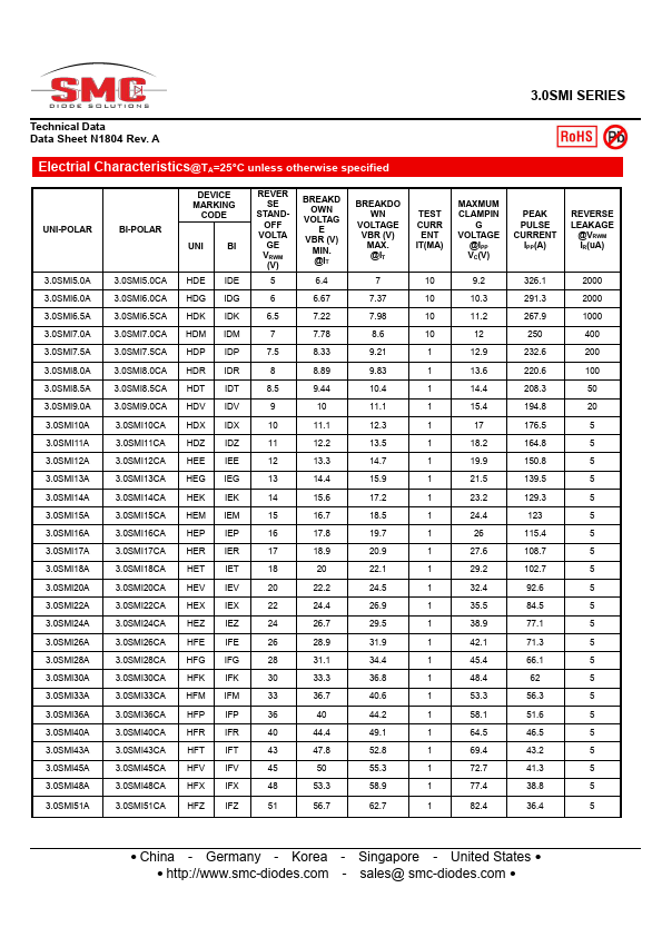
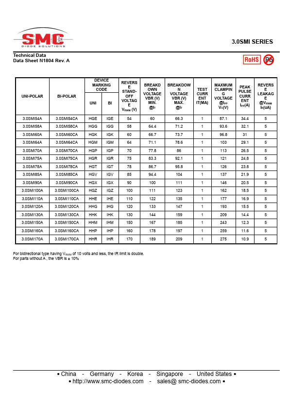
SMC Diode 3.0SMI12A
SURFACE MOUNT TRANSIENT VOLTAGESUPPRESSOR
| Part No. | 3.0SMI12A |
|---|---|
| Datasheet | 3.0SMI12A Download |
| Manufacturer |  SMC Diode |
| Description | SURFACE MOUNT TRANSIENT VOLTAGESUPPRESSOR |
| Buy | Stock & Price |
FEATURES
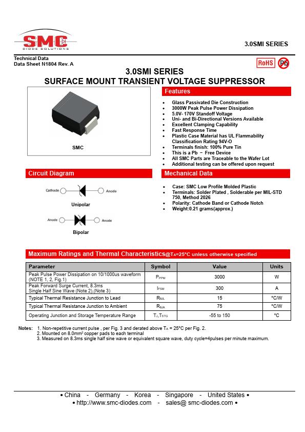
SMC Circuit Diagram● Glass Passivated Die Construction
● 3000W Peak Pulse Power Dissipation
● 5.0V- 170V Standoff Voltage
● Uni- and Bi-Directional Versions Available
● Excellent Clamping Capability
● Fast Response Time
● Plastic Case Material has UL Flammability Classification Rating 94V-O
● Terminals finish: 100% Pure Tin
● This is a Pb − Free Device
● All SMC Parts are Traceable to the Wafer Lot
● Additional testing can be offered upon request
MECHANICAL DATA
Unipolar● Case: SMC Low Profile Molded Plastic
● Terminals: Solder Plated , Solderable per MIL-STD 750, Method 2026
● Polarity: Cathode Band or Cathode Notch
● Weight:0.21 grams(approx.)
● Bipolar
MAXIMUM RATINGS
and Thermal Characteristics@TA=25°C unless otherwise specified Parameter Peak Pulse Power Dissipation on 10/1000us waveform (NOTE 1, 2, Fig.1) Peak Forward Surge Current, 8.3ms Single Half Sine Wave (Note 2),(Note 3) Typical Thermal Resistance Junction to Lead Typical Thermal Resistance Junction to Ambient Operating Junction and Storage Temperature Range Symbol PPPM IFSM RθJL RθJA TJ,TSTG Value 3000 300 15 75 -55 to 150 Units W A °C/W °C/W °C Notes: 1.