SM240W Overview
Description
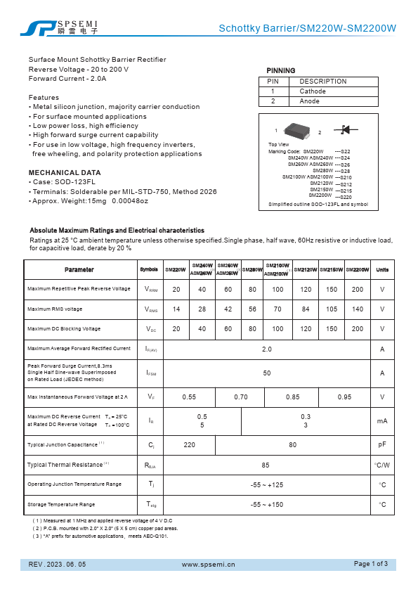
1 Cathode 2 Anode 1 2 Top View Marking Code: SM220W ---S22 SM240W ASM240W ---S24 SM260W ASM260W ---S26 SM280W ---S28 SM2100W ASM2100W ---S210 SM2120W ---S212 SM2150W ---S215 SM2200W ---S220 Simplified outline SOD-123FL and symbol Ratings at 25 °C ambient temperature unless otherwise phase, half wave, 60Hz resistive or inductive load, for capacitive load, derate by 20 % Parameter Symbols SM240W SM260W SM2100W SM220W ASM240W(3)ASM260W(3)SM280W (3) ASM2100W SM2120W SM2150W SM2200W Units Maximum Repetitive Peak Reverse Voltage VRRM 20 40 60 80 100 120 150 200 V Maximum RMS voltage VRMS 14 28 42 56 70 84 105 140 V Maximum DC Blocking Voltage VDC 20 40 60 80 100 120 150 200 V Maximum Average Forward Rectified Current Peak Forward Surge Current,8.3ms Single Half Sine-wave Superimposed on Rated Load (JEDEC method) Max Instantaneous Forward Voltage at 2 A I F ( AV ) IFSM VF 0.55 2.0 50 0.70 0.85 A A 0.95 V Maximum DC Reverse Current Ta = 25°C at Rated DC Reverse Voltage Ta =100°C IR 0.5 5 0.3 3 mA Typical Junction Capacitance(1) Cj 220 80 pF Typical RθJA Tj 85 -55 ~ +125 °C/W °C Storage Temperature Range Tstg -55 ~ +150 °C (1)Measured at 1 MHz and applied reverse voltage of 4 V.
Key Features
- Metal silicon junction, majority carrier conduction
- For surface mounted applications
- Low power loss, high efficiency
- High forward surge current capability
- For use in low voltage, high frequency inverters, free wheeling, and polarity protection applications MECHANICAL DATA
- Case: SOD-123FL
- Terminals: Solderable per MIL-STD-750, Method 2026
- Approx. Weight:15mg 0.00048oz PINNING PIN