M3493B1
M3493B1 is CMOS 12 X 8 CROSSPOINTWITH CONTROL MEMORY manufactured by STMicroelectronics.
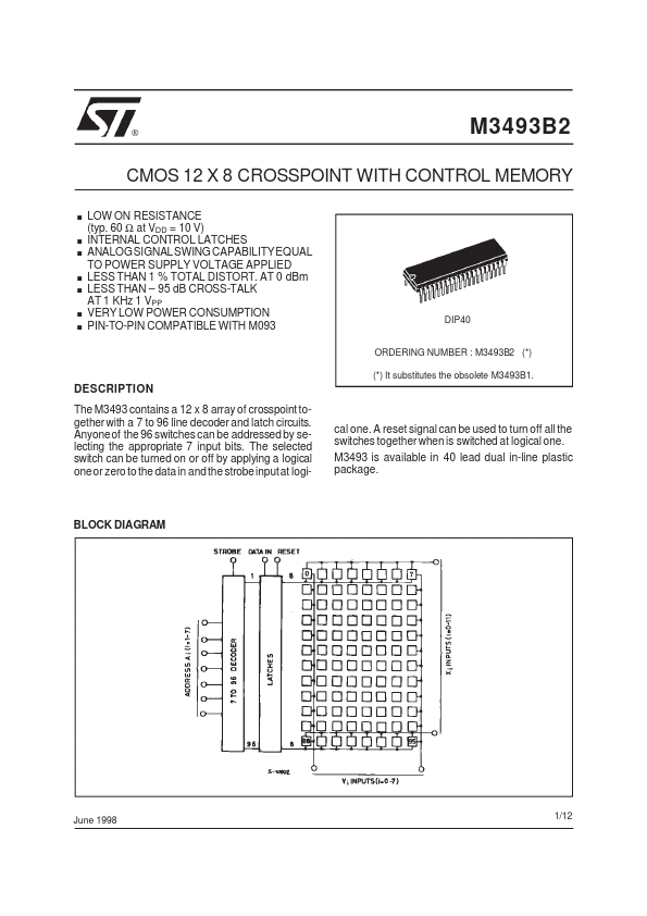
DESCRIPTION
The M3493 contains a 12 x 8 array of crosspoint together with a 7 to 96 line decoder and latch circuits. Anyoneof the 96 switches can be addressed by selecting the appropriate 7 input bits. The selected switch can be turned on or off by applying a logical oneor zero to the data in and the strobeinputat logi- cal one. A reset signal can be used to turn off all the switches together when is switched at logical one. M3493 is available in 40 lead dual in-line plastic package.
BLOCK DIAGRAM
June 1998
1/12
M3493B2
PIN CONNECTION (top view)
INPUT/OUTPUT DESCRIPTION
I/O POWER I I ADDRESS I I AX0-AX3 AY0-AY2 4, 5, 22, 23 2, 24, 25 X Address Lines. These 4 pins are used to select one of the 12 rows of switches. Refer to the truth table for legal address. Y Address Lines. These 3 pins are used to select one of the 8 columns of switches. Refer to the truth table for legal address. VDD VSS 40 20 Positive Power Supply Negative Power Supply Symbol Pin Description
CONTROL I DATA 38 This input determines if the selected switch will be turned on (closed) or off (opened). If the pin is held high, the selected switch will be closed. If the pin is held low, the switch will be opened. This pin enables whatever action is selected by the ADDRESS and DATA pins. When the STROBE pin is held low, no switch openings or closings take place. When the STROBE pin is held high, the switch addressed by the select lines will be opened or closed (depending upon the state of the DATA pin) Master Reset. This pin turns off (opens) all 96 switches. The states of the above control lines are irreleant. This pin is active high.
STROBE
I DATA I/O I/O
RESET
X0-X11 Y0-Y7
8-13, 28-33 1,15,17,19,21 35,37,39
Analog Input/Outputs. These pins are connected to the Y0-Y7 pins in according to the truth table. Analog Input/Outputs. These pins are connected to the X0-X15 pins in according to the truth table.
2/12
M3493B2
TRUTH TABLE
AX0 0 1 0 1 0 1 0- 1- 0 1 0 1 0 1 0- 1- 0 ↓ 1 0 ↓ 1...