TD340
TD340 is H-BRIDGE QUAD POWER MOSFET DRIVER FOR DC MOTOR CONTROL manufactured by STMicroelectronics.
DESCRIPTION
The TD340 integrated circuit allows N-Channel Power Mosfets driving in a full H-bridge configuration and is best suited for DC Motor Control Applications. The four drivers outputs are designed to allow 25k Hz MOSFET switching. The speed and direction of the motor are to be set by two pins. Voltage across the motor is controlled by low side Pulse Width Modulation (PWM). This PWM feature can be made internally when the input pin is connected to an analog signal, or it can be given directly from a digital source. An internal charge pump allows proper upper MOS driving for full static operation (100% PWM). TD340 achieves very low EMI noise thanks to its balanced charge pump structure and its drivers moderate slew rate. To avoid excessive heating due to free wheeling, appropriate synchronous rectification is achieved on the corresponding High Side MOSFET. Moreover, TD340 integrates a 5V voltage regulator suitable as a power supply output for the microcontroller, a Reset circuit and a Watchdog circuit. Security functions disable the TD340 (MOS off) when abnormal conditions occur like overvoltage, undervoltage or CPU loss of control (watchdog). TD340 withstands transients as met in automotive field without special protection devices thanks to its 60V BCD technology.
May 2000
ORDER CODE
Package Part Number TD340ID Temperature Range -40° C, +125° C D
- D = Small Outline Package (SO)
- also available in Tape & Reel (DT)
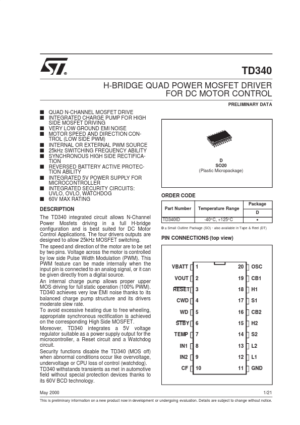
PIN CONNECTIONS (top view)
VBATT VOUT RESET CWD WD STBY TEMP IN1 IN2 CF
1 2 3 4 5 6 7 8 9 10
20 19 18 17 16 15 14 13 12 11
OSC CB1 H1 S1 CB2 H2 S2 L2 L1 GND
1/21
This is preliminary information on a new product now in development or undergoing evaluation. Details are subject to change without notice.
SYSTEM AND INTERNAL BLOCK DIAGRAM
BATT + VBATT 5V VOUT RESET
RESET
SUPPLY UVLO OVLO
OSC CB1 H1
CWD µCONTROLLER WD STBY TEMP IN1 IN2 CF 0V T°
WATCHDOG
S1 CB2
PWM LOGIC
H2 S2 L2 L1
Q2H M Q2L
Q1H
Q1L
GND BATT
- PIN...