DESCRIPTION
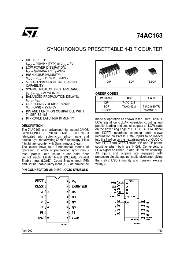
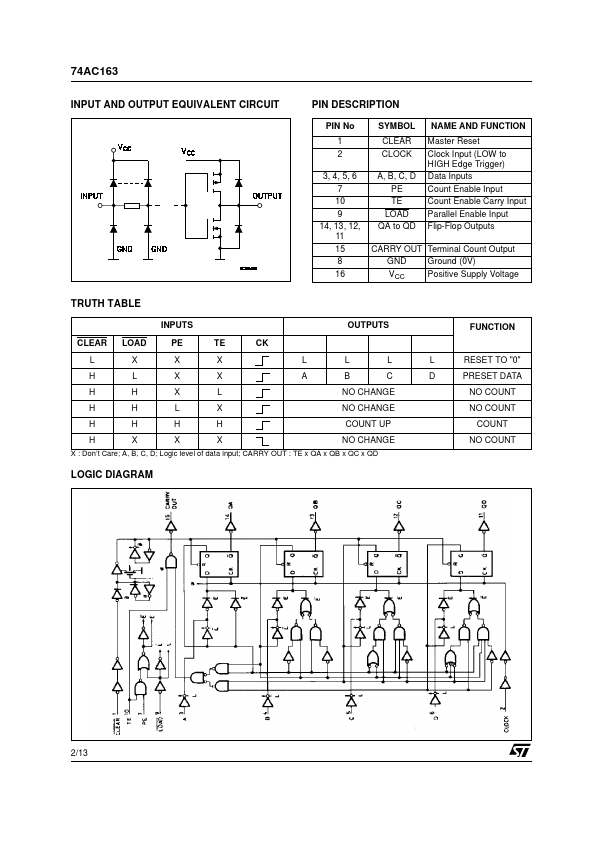
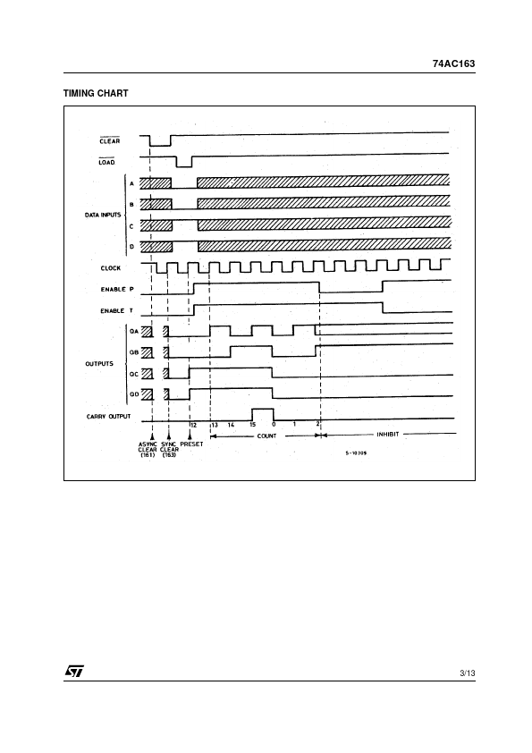
Four control inputs, Master Reset (CLEAR), Parallel Enable Input (LOAD), Count Enable Input (PE) and Count Enable Carry Input (TE), determine the PIN CONNECTION AND IEC LOGIC SYMBOLS mode of operation as shown in the Truth Table. A LOW signal on CLEAR overrides counting and parallel loading and sets all outputs on LOW state on the next rising edge of CLOCK. A LOW signal on LOAD overrides counting and allows information on Parallel Data inputs to be loaded into the flip-flop on the next rising edge of CLOCK. With LOAD and CLEAR HIGH, PE and TE permit counting when both are HIGH. Conversely, a LOW signal on either PE and TE inhibits counting. All inputs and outputs are equipped with protection circuits against static discharge, giving them 2KV ESD immunity and transient excess voltage. April 2001 1/13 74AC163 INPUT AND OUTPUT EQUIVALENT CIRCUIT PIN DESCRIPTION
PIN No 1 2 3, 4, 5, 6 7 10 9 14, 13, 12, 11 15 8 16 SYMBOL CLEAR CLOCK A, B, C, D PE TE LOAD QA to QD NAME AND FUNCTI... STMicroelectronics