DESCRIPTION
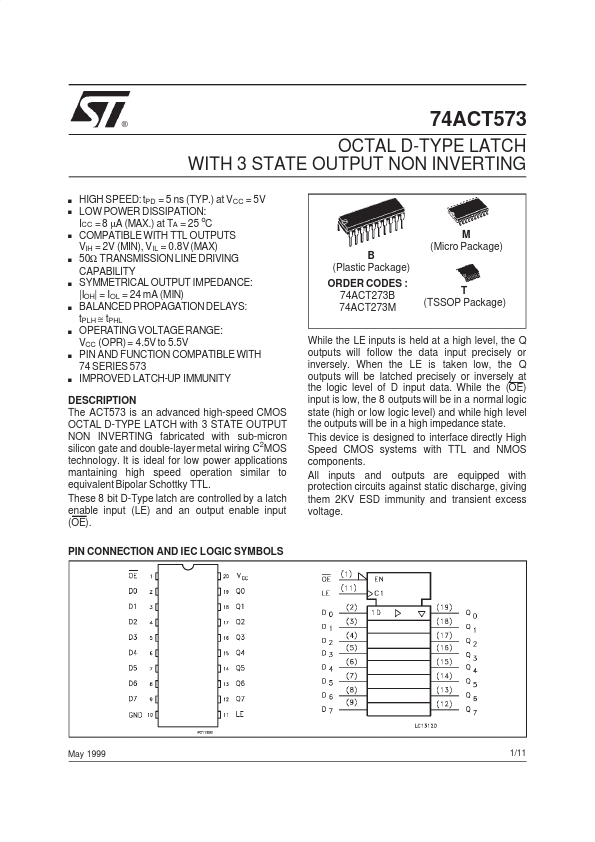
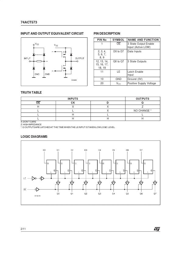
These 8 bit D-Type latch are controlled by a latch enable input (LE) and an output enable input (OE). PIN CONNECTION AND IEC LOGIC SYMBOLS While the LE inputs is held at a high level, the Q outputs will follow the data input precisely or inversely. When the LE is taken low, the Q outputs will be latched precisely or inversely at the logic level of D input data. While the (OE) input is low, the 8 outputs will be in a normal logic state (high or low logic level) and while high level the outputs will be in a high impedance state. This device is designed to interface directly High Speed CMOS systems with TTL and NMOS components. All inputs and outputs are equipped with protection circuits against static discharge, giving them 2KV ESD immunity and transient excess voltage. May 1999 1/11 74ACT573 INPUT AND OUTPUT EQUIVALENT CIRCUIT PIN DESCRIPTION
PIN No 1 2, 3, 4, 5, 6, 7, 8, 9 12, 13, 14, 15, 16, 17, 18, 19 11 10 20 SYMBOL OE D0 to D7 NAME AND FUNCT ION 3 State Output Enable In... STMicroelectronics