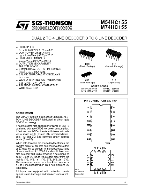
DESCRIPTION
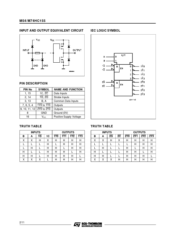
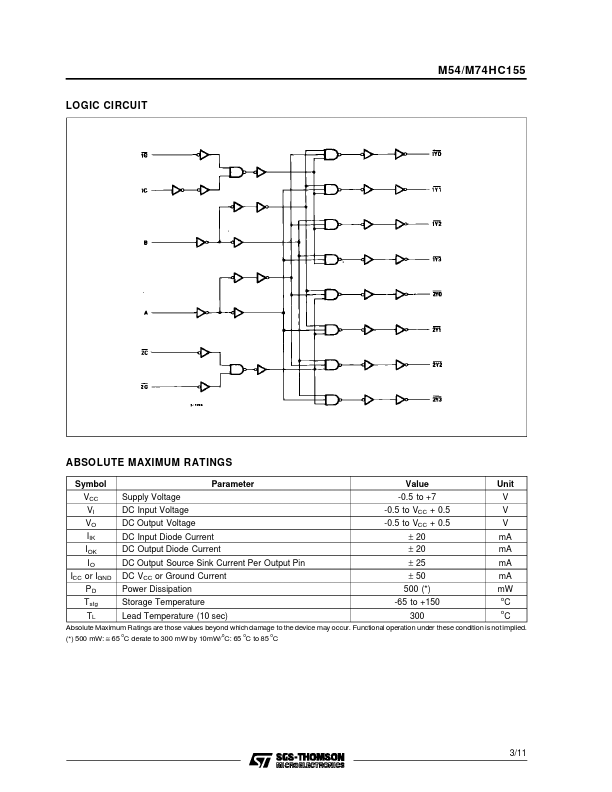
It features dual 1-TO-4 line demultiplexers with individual strobe inputs (1G and 2G), individual data inputs (1C and 2C) and common binary address inputs (A and B). When both decoders are enabled by the strobes, the inverted output of 1C data and non-inverted output of 2C data will be brought to the select output pins of each sections. A 1-TO-8 line demultiplexer can also be easily built up by providing a data signal to both 1C and 2C inputs ; the output order from the msb is 1Y3, 1Y2, 1Y1, 1Y0, 2Y3, 2Y2, 2Y1, 2Y0. This device can be used as a 2-to-4 line decoder or a 3-to-8 line decoder when 1C is held high and 2C is held low. All inputs are equipped with protection circuits against static discharge and transient excess voltage. December 1992 NC = No Internal Connection 1/11 M54/M74HC155 INPUT AND OUTPUT EQUIVALENT CIRCUIT IEC LOGIC SYMBOL PIN DESCRIPTION
PIN No 1, 15 2, 14 3, 13 7, 6, 5, 4 SYMBOL 1C, 2C 1G, 2G B, A 1Y0 to 1Y3 NAME AND FUNCTION Data Inputs Strobe Inputs C... STMicroelectronics