DESCRIPTION
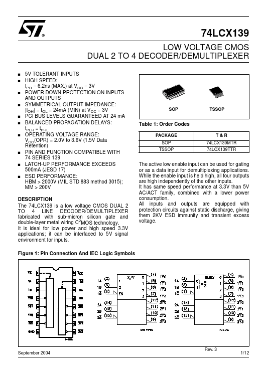
Figure 1: Pin Connection And IEC Logic Symbols The active low enable input can be used for gating or as a data input for demultiplexing applications. While the enable input is held high, all four outputs are high independently of the other inputs. All inputs and outputs are equipped with protection circuits against static discharge, giving them 2KV ESD immunity and transient excess voltage. September 2004 Rev. 3 1/12 74LCX139 Figure 2: Input And Output Equivalent Circuit Table 2: Pin DESCRIPTION
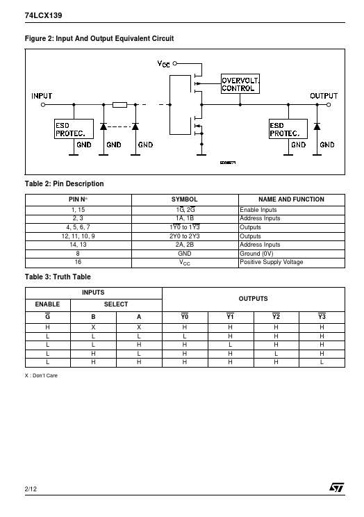
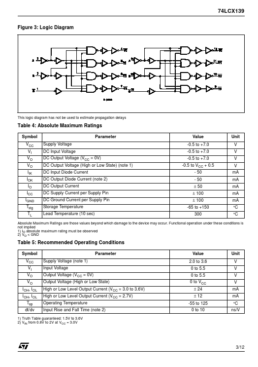
PIN N° 1, 15 2, 3 4, 5, 6, 7 12, 11, 10, 9 14, 13 8 16 SYMBOL 1G, 2G 1A, 1B 1Y0 to 1Y3 2Y0 to 2Y3 2A, 2B GND VCC NAME AND FUNCTION Enable Inputs Address Inputs Outputs Outputs Address Inputs Ground (0V) Positive Supply Voltage Table 3: Truth Table INPUTS OUTPUTS ENABLE G H L L L L X : Don’t Care SELECT B X L L H H A X L H L H Y0 H L H H H Y1 H H L H H Y2 H H H L H Y3 H H H H L 2/12 74LCX139 Figure 3: Logic Diagram This logic diagram has not be used to estimate propagation delays Tab... STMicroelectronics