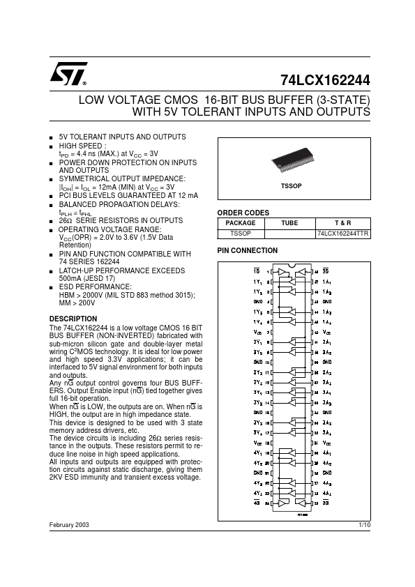
DESCRIPTION
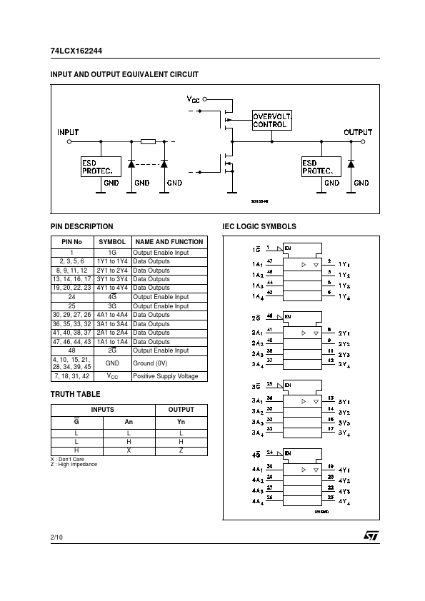
Any nG output control governs four BUS BUFFERS. Output Enable input (nG) tied together gives full 16-bit operation. When nG is LOW, the outputs are on. When nG is HIGH, the output are in high impedance state. This device is designed to be used with 3 state memory address drivers, etc. The device circuits is including 26Ω series resistance in the outputs. These resistors permit to reduce line noise in high speed applications. All inputs and outputs are equipped with protection circuits against static discharge, giving them 2KV ESD immunity and transient excess voltage. February 2003 1/10 74LCX162244 INPUT AND OUTPUT EQUIVALENT CIRCUIT PIN DESCRIPTION
PIN No 1 2, 3, 5, 6 8, 9, 11, 12 13, 14, 16, 17 19, 20, 22, 23 24 25 30, 29, 27, 26 36, 35, 33, 32 41, 40, 38, 37 47, 46, 44, 43 48 4, 10, 15, 21, 28, 34, 39, 45 7, 18, 31, 42 SYMBOL 1G 1Y1 to 1Y4 2Y1 to 2Y4 3Y1 to 3Y4 4Y1 to 4Y4 4G 3G 4A1 to 4A4 3A1 to 3A4 2A1 to 2A4 1A1 to 1A4 2G GND VCC NAME AND FUNCTION Output Enable Input D... STMicroelectronics