DESCRIPTION
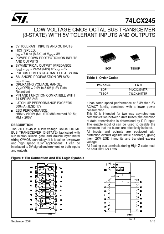
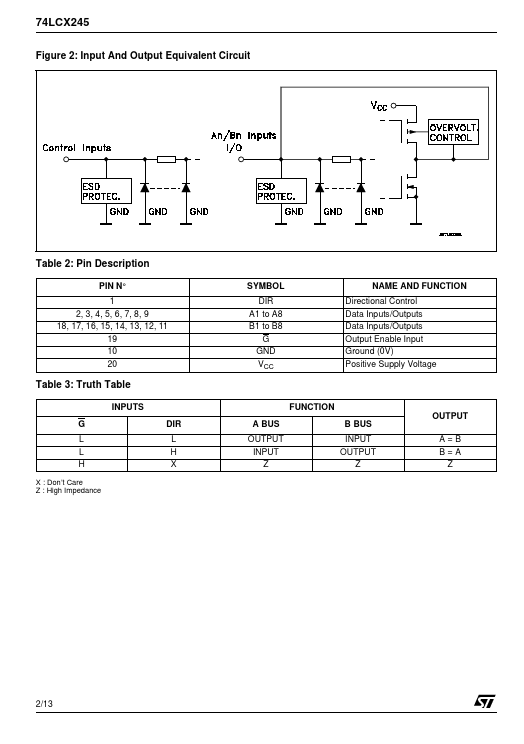
Figure 1: Pin Connection And IEC Logic Symbols It has same speed performance at 3.3V than 5V AC/ACT family, combined with a lower power consumption. The enable input G can be used to disable the device so that the buses are effectively isolated. All inputs and outputs are equipped with protection circuits against static discharge, giving them 2KV ESD immunity and transient excess voltage. All floating bus terminals during High Z state must be held HIGH or LOW. September 2004 Rev. 4 1/13 74LCX245 Figure 2: Input And Output Equivalent Circuit Table 2: Pin DESCRIPTION
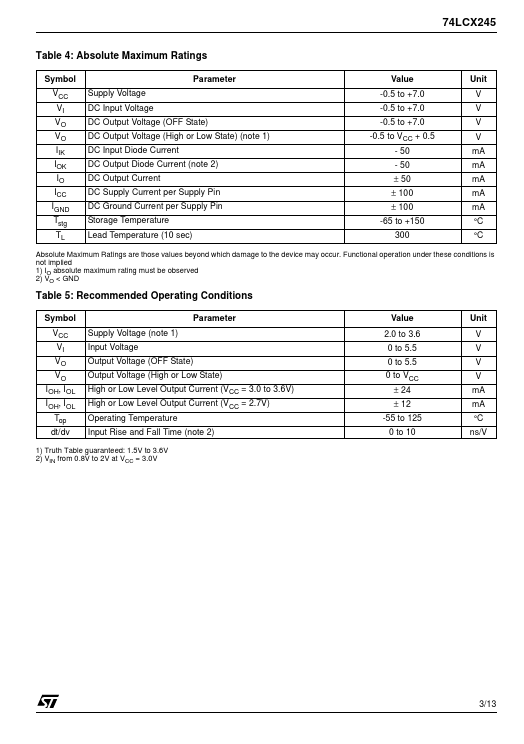
PIN N° 1 2, 3, 4, 5, 6, 7, 8, 9 18, 17, 16, 15, 14, 13, 12, 11 19 10 20 SYMBOL DIR A1 to A8 B1 to B8 G GND VCC NAME AND FUNCTION Directional Control Data Inputs/Outputs Data Inputs/Outputs Output Enable Input Ground (0V) Positive Supply Voltage Table 3: Truth Table INPUTS G L L H X : Don’t Care Z : High Impedance FUNCTION OUTPUT DIR L H X A BUS OUTPUT INPUT Z B BUS INPUT OUTPUT Z A=B B=A Z 2/13 74LCX245 Table 4:... STMicroelectronics