DESCRIPTION
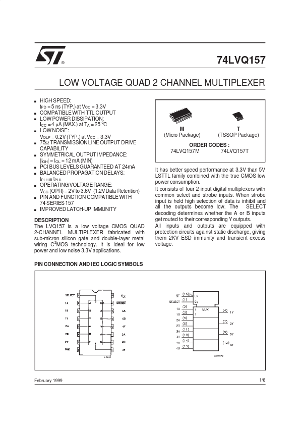
PIN CONNECTION AND IEC LOGIC SYMBOLS It has better speed performance at 3.3V than 5V LSTTL family combined with the true CMOS low power consumption. It consists of four 2-input digital multiplexers with common select and strobe inputs. When strobe input is held high selection of data is inhibit and all the outputs become low. The SELECT decoding determines whether the A or B inputs get routed to their corresponding Y outputs. All inputs and outputs are equipped with protection circuits against static discharge, giving them 2KV ESD immunity and transient excess voltage. February 1999 1/8 74LVQ157 INPUT AND OUTPUT EQUIVALENT CIRCUIT PIN DESCRIPTION
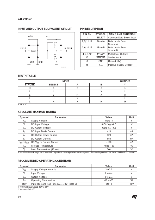
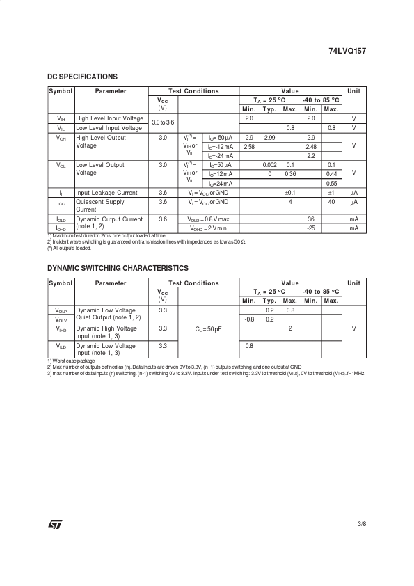
PIN No 1 2, 5, 11, 14 3, 6, 10, 13 4, 7,9, 12 15 8 16 SYMBOL SELECT 1A to 4A 1B to 4B 1Y to 4Y STROBE GND VCC NAME AND FUNCT ION Common Data Select Input Data Inputs From Source A Data Inputs From Source B Multiplexer Outputs Strobe Input Ground (0V) Positive Supply Voltage TRUTH TABLE INPUT STROBE H L L L L X:”H” or ”L” OUT PUT A... STMicroelectronics