DESCRIPTION
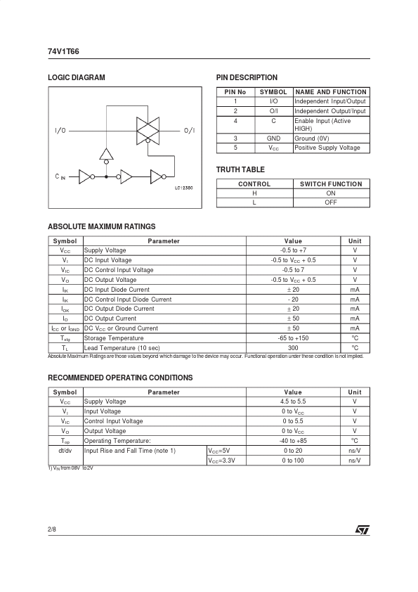
This bilateral switch handles rail to rail analog and digital signals that may vary across the full power-supply range (from Vcc to Ground). The C input is provided to control the switch and it’s compatible with standard TTL output; the switch is ON when the C input is held high and off when C is held low. It can be used in many application as Battery Powered System, Audio Signal Routing, Communications System, Test Equipment. It’s available in the commercial temperature range in SOT23-5L and SC-70-5L package. PIN CONNECTION AND IEC LOGIC SYMBOLS February 2000 1/8 74V1T66 LOGIC DIAGRAM PIN DESCRIPTION
PIN No 1 2 4 3 5 SYMBOL I/O O/I C GND VCC NAME AND FUNCT ION Independent Input/Output Independent Output/Input Enable Input (Active HIGH) Ground (0V) Positive Supply Voltage TRUTH TABLE CONTROL H L SWITCH F UNCTIO N ON OFF ABSOLUTE MAXIMUM RATINGS
Symbol VCC VI V IC VO IIK IIK IOK IO Tstg TL Supply Voltage DC Input Voltage DC Control Input Voltage DC Output Voltage DC Input Diode Current DC Control Input Diode Current DC Output Diode Current DC Output Current Storage Temperature Lead Temperature (10 sec) Parameter Value -0. STMicroelectronics