DESCRIPTION
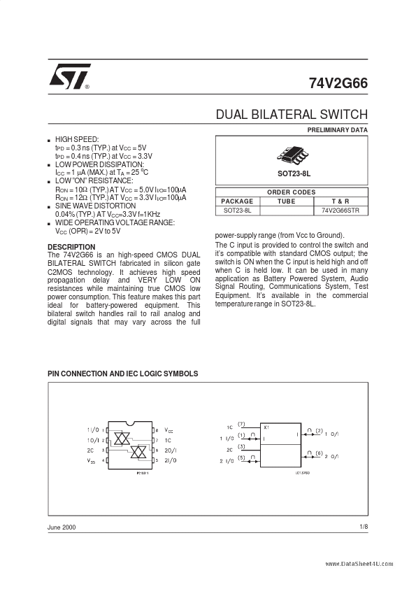
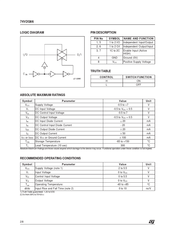
This bilateral switch handles rail to rail analog and digital signals that may vary across the full power-supply range (from Vcc to Ground). The C input is provided to control the switch and it’s compatible with standard CMOS output; the switch is ON when the C input is held high and off when C is held low. It can be used in many application as Battery Powered System, Audio Signal Routing, Communications System, Test Equipment. It’s available in the commercial temperature range in SOT23-8L. PIN CONNECTION AND IEC LOGIC SYMBOLS June 2000 1/8 74V2G66 LOGIC DIAGRAM PIN DESCRIPTION
PIN No 1, 5 2, 6 3, 7 4 8 SYMBOL 1 to 2 I/O 1 to 2 O/I 1C to 2C GND VCC NAME AND FUNCT ION Independent Input/Output Independent Output/Input Enable Input (Active HIGH) Ground (0V) Positive Supply Voltage TRUTH TABLE CONTROL H L SWITCH F UNCTIO N ON OFF ABSOLUTE MAXIMUM RATINGS
Symbol VCC VI V IC VO IIK IIK IOK IO Tstg TL Supply Voltage DC Input Voltage DC Control Input Voltage DC Output Voltage DC In... STMicroelectronics