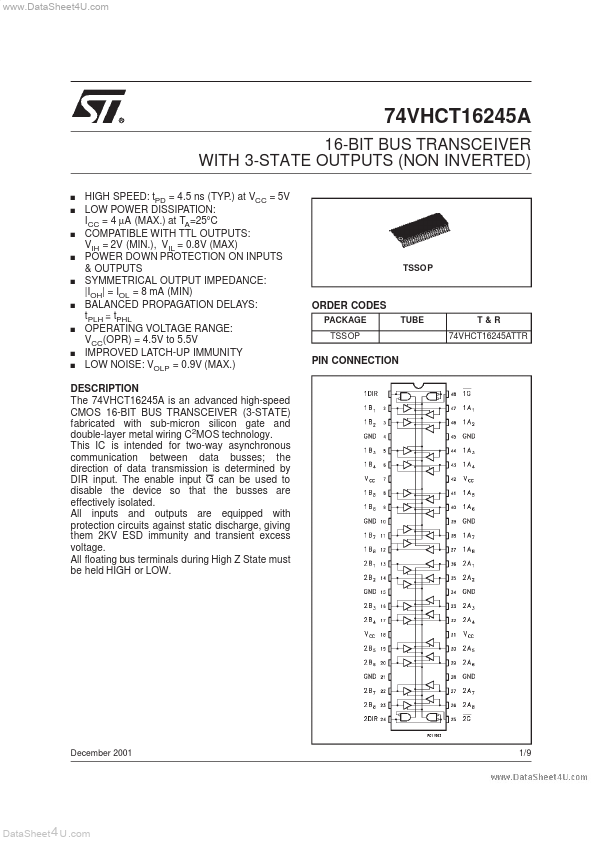
DESCRIPTION
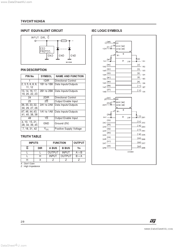
All inputs and outputs are equipped with protection circuits against static discharge, giving them 2KV ESD immunity and transient excess voltage. All floating bus terminals during High Z State must be held HIGH or LOW. December 2001 1/9 DataSheet 4 U .com 74VCHT16245A INPUT EQUIVALENT CIRCUIT IEC LOGIC SYMBOLS PIN DESCRIPTION
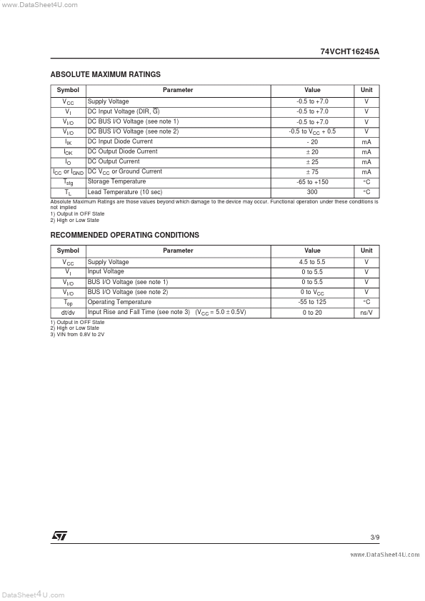
PIN No 1 2, 3, 5, 6, 8, 9, 11, 12 13, 14, 16, 17, 19, 20, 22, 23 24 25 36, 35, 33, 32, 30, 29, 27, 26 47, 46, 44, 43, 41, 40, 38, 38 48 4, 10, 15, 21, 28, 34, 39, 45 7, 18, 31, 42 SYMBOL NAME AND FUNCTION 1DIR Directional Control 1B1 to 1B8 Data Inputs/Outputs 2B1 to 2B8 Data Inputs/Outputs 2DIR Directional Control 2G Output Enable Input 2A1 to 2A8 Data Inputs/Outputs 1A1 to 1A8 Data Inputs/Outputs 1G GND VCC Output Enable Input Ground (0V) Positive Supply Voltage TRUTH TABLE INPUTS G L L H DIR L H X FUNCTION A BUS B BUS OUTPUT Yn A =B B =A Z OUTPUT INPUT INPUT OUTPUT Z Z X : Don‘t Care Z : High Impedance 2/9 DataSheet 4 U .com 74VCHT16245A ABSOLUTE MA... STMicroelectronics