DESCRIPTION
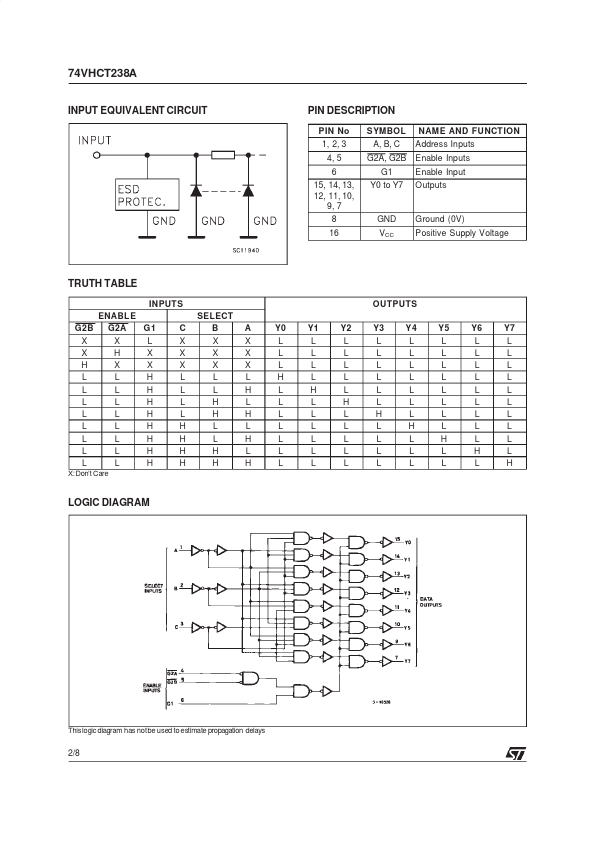
If the device is enabled, 3 binary select inputs (A, B and C) determine which one of the outputs will go high. If enable input G1 is held low or either G2A or G2B is held high, decoding function is inhibited and all the 8 outputs go to low. Three enable inputs are provided to ease cascade connection and application of this address decoders for memory systems. Power down protection is provided on all inputs and outputs and 0 to 7V can be accepted on inputs with no regard to the supply voltage. This device can be used to interface 5V to 3V. All inputs and outputs are equipped with protection circuits against static discharge, giving them 2KV ESD immunity and transient excess voltage. PIN CONNECTION AND IEC LOGIC SYMBOLS March 2000 1/8 74VHCT238A INPUT EQUIVALENT CIRCUIT PIN DESCRIPTION
PIN No 1, 2, 3 4, 5 6 15, 14, 13, 12, 11, 10, 9, 7 8 16 SYMBOL A, B, C G2A, G2B G1 Y0 to Y7 NAME AND FUNCT ION Address Inputs Enable Inputs Enable Input Outputs GND VCC Ground (0V) Positive Sup... STMicroelectronics