FEATURES AND BENEFITS
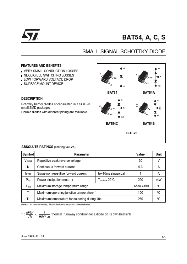
A K1 A VERY SMALL CONDUCTION LOSSES NEGLIGIBLE SWITCHING LOSSES LOW FORWARD VOLTAGE DROP SURFACE MOUNT DEVICE K Nc A K1 K2 A K K2 BAT54 DESCRIPTION
Schottky barrier diodes encapsulated in a SOT-23 small SMD packages. Double diodes with different pining are available. K A1 A2 A2 A1 A1 K2 BAT54A A2 K K1 A2 A1 K2 K1 BAT54C SOT-23 BAT54S ABSOLUTE RATINGS (limiting values) Symbol VRRM IF IFSM Ptot Tstg Tj TL Parameter Repetitive peak reverse voltage Continuous forward current Surge non repetitive forward current Power dissipation (note 1) Maximum storage temperature range Maximum operating junction temperature * Maximum temperature for soldering during 10s tp=10ms sinusoidal Tamb = 25°C Value 30 0.3 1 250 - 65 to +150 150 260 Unit V A A mW °C °C °C Note 1: for double diodes, Ptot is the total dissipation of both diodes. * : dPtot 1 < thermal runaway condition for a diode on its own heatsink Rth(j−a) dTj June 1999 - Ed: 3A 1/5 BAT54, A, C, S THERMAL RESISTANCE Symbol Rth (j-a) Junction to ambient (*) Parameter Value 500 Unit °C/W (*) Mounted on epoxy board with recommended pad layout. STMicroelectronics