DESCRIPTION
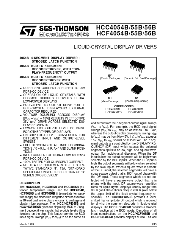
OF ”B” SERIES CMOS DEVICES” EY (Plastic Package) F (Ceramic Frit Seal Package) . . . . . . . . . . M1 (Micro Package) C1 (Plastic Chip Carrier) ORDER CODES : HCC40XXBF HCF40XXBM1 HCF40XXBEY HCF40XXBC1 DESCRIPTION
For example, the BCD input-signal swings (VDD to VSS) may be as low as 0 to – 3V, whereas the output-display drive-signal swing (VDD to VEE) may be from 0 to – 5V. If VDD to VEE exceeds 15V, VDD to VSS should be at least 4V. The 7-segment outputs are controlled by the DISPLAY-FREQUENCY (DF) input which causes the selected segment outputs to be low, high, or a square-wave output (for liquid-crystal displays). When the DF input is low the output segments will be high when selected by the BCD inputs. When the DF input is high, the output segments will be low when selected by the BCD inputs. When a square-wave is present at the DF input, the selected segments will have a square-wave output that is 180° out of phase with the DF input. Those segments which are not selected will have a square-wave output that is in phase with the input. STMicroelectronics