STMicroelectronics HCF4514B
The HCC 4514B/HCC4515B (extended temperature range) and the HCF 4514B/HCF4515B (intermediate temperature range) are monolithic integrated circuits available in 24-lead dual in-line plastic or ceramic package and plastic micro package. The HCC/HCF4514B/4515B consisting of a 4-bit strobed latch and a 4 to 16 line decoder.| Part No. | HCF4514B |
|---|---|
| Datasheet | HCF4514B Download |
| Manufacturer |  STMicroelectronics |
| Description | 4-BIT LATCH/4-TO-16 LINE DECODER |
| Buy | Stock & Price |
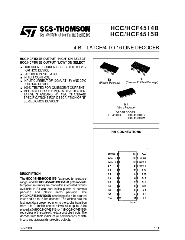
DESCRIPTION
OF ”B” SERIES CMOS DEVICES” EY (Plastic Package) F (Ceramic Frit Seal Package) M1 (Micro Package) ORDER CODES : HCC45XXBF HCF45XXBEY HCF45XXBM1 PIN CONNECTIONSDESCRIPTION
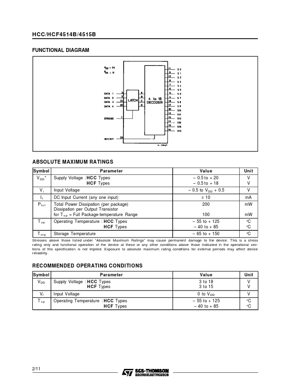
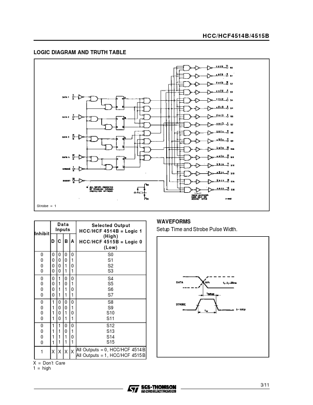
The latches hold the last input data presented prior to the strobe transition from 1 to 0. Inhibit control allows all outputs to be placed at 0 (HCC/HCF4514B)or 1 (HCC/HCF4515B) regardless of the state ofthe data or strobe inputs. The decode truth table indicates all combinations of data inputs and appropriate selected outputs. June 1989 1/11 HCC/HCF4514B/4515B FUNCTIONAL DIAGRAMABSOLUTE MAXIMUM RATINGS
Symbol V DD * Vi II Pto t Parameter Supply Voltage : HC C Types H C F Types Input Voltage DC Input Current (any one input) Total Power Dissipation (per package) Dissipation per Output Transistor for T o p = Full Package-temperature Range Operating Temperature : HCC Types H CF Types Storage Temperature Value – 0.5 to + 20 – 0.5 to + 18 – 0.5 to V DD + 0.5 ± 10 200 100 – 55 to + 125 – 40 to + 85 – 65 to + 150 Unit V V V mA mW mW °C °C °C T op T stg Stresses above those listed under ”ABSOLUTE MAXIMUM RATINGS
” may cause permanent damage to the device.