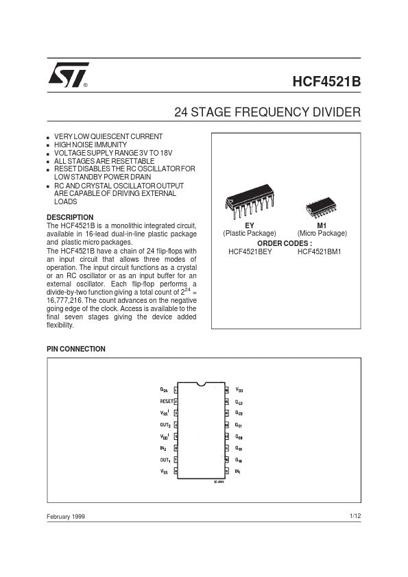
DESCRIPTION
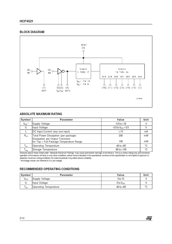
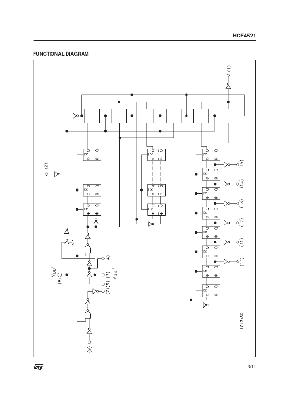
Each flip-flop performs a divide-by-two function giving a total count of 224 = 16,777,216. The count advances on the negative going edge of the clock. Access is available to the final seven stages giving the device added flexibility. PIN CONNECTION February 1999 1/12 HCF4521 BLOCK DIAGRAM ABSOLUTE MAXIMUM RATING Symbol VDD * Vi II Ptot Supply Voltage Input Voltage DC Input Current (any one input) Total Power Dissipation (per package) Dissipation per Output Transistor for Top = Full Package Temperature Range Operating Temperature Storage Temperature Parameter Value -0.5 to +18 -0.5 to VDD + 0.5 ± 10 200 100 -40 to +85 -65 to +150 Unit V V mA mW mW o o Top Tstg C C Stresses above those listedunder ”ABSOLUTE MAXIMUM RATINGS
” may cause permanent damage to the device. This is a stress rating only and functional operation ofthe device atthese or any other conditions above those indicated in the operational sections of this specification is not implied. Exposure to absolute maximum ratingconditions for external periods may affect device reliability. * Allvoltage values are referred to VSS pin voltage. STMicroelectronics