DESCRIPTION
OF ’ B ’ SERIES CMOS DEVICES” DESCRIPTION
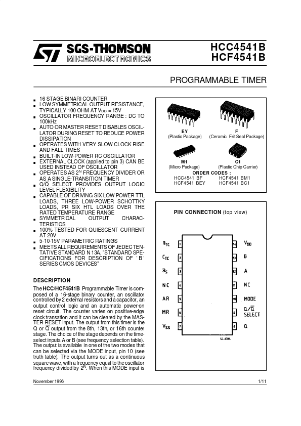
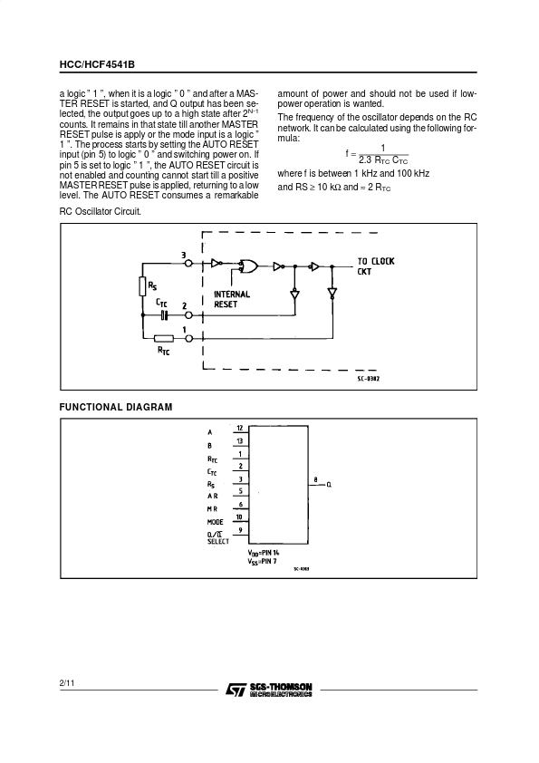
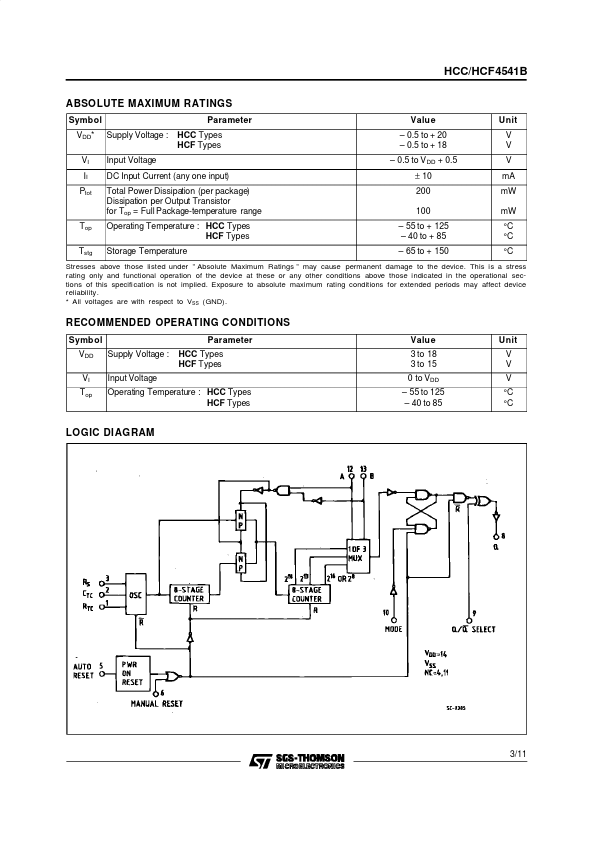
The output from this timer is the Q or Q output from the 8th, 13th, or 16th counter stage. The choice of the stage depends on the timeselect inputs A or B (see frequency selection table). The output is available in one of the two modes that can be selected via the MODE input, pin 10 (see truth table). The output turns out as a continuous square wave, with a frequency equal to the oscillator frequency divided by 2N. When this MODE input is November 1996 1/11 EY (Plastic Package) F (Ceramic Frit Seal Package) M1 C1 (Micro Package) (Plastic Chip Carrier) ORDER CODES : HCC4541 BF HCF4541 BM1 HCF4541 BEY HCF4541 BC1 PIN CONNECTION (top view) HCC/HCF4541B a logic ” 1 ”, when it is a logic ” 0 ” and after a MASTER RESET is started, and Q output has been selected, the output goes up to a high state after 2N-1 counts. It remains in that state till another MASTER RESET pulse is apply or the mode input is a logic ” 1 ”. The process starts by setting the AUTO RESET input (pin 5) to logic ” 0 ” and switching power on. STMicroelectronics