DESCRIPTION
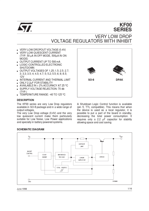
SCHEMATIC DIAGRAM A Shutdown Logic Control function is available (pin 5, TTL compatible). This means that when the device is used as a local regulator, it is possible to put a part of the board in standby, decreasing the total power consumption. It requires only a 2.2 µF capacitor for stability allowing space and cost saving. June 1998 1/16 KF00 ABSOLUTE MAXIMUM RATINGS
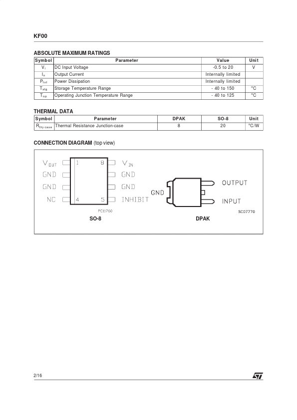
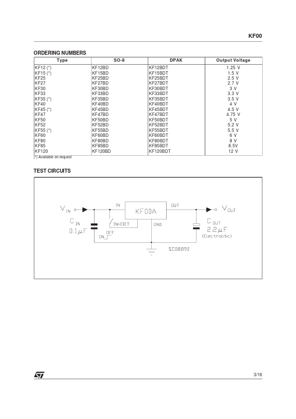
Symb ol Vi Io Pt ot T stg To p DC Input Voltage Output Current Power Dissipation Storage Temperature Range Operating Junction Temperature Range Parameter Value -0.5 to 20 Internally limited Internally limited - 40 to 150 - 40 to 125 o o Uni t V C C THERMAL DATA Symb ol Parameter DPAK 8 SO-8 20 Unit o R t hj- case Thermal Resistance Junction-case C/W CONNECTION DIAGRAM (top view) SO-8 DPAK 2/16 KF00 ORDERING NUMBERS T ype KF12 (*) KF15 (*) KF25 KF27 KF30 KF33 KF35 (*) KF40 KF45 (*) KF47 KF50 KF52 KF55 (*) KF60 KF80 KF85 KF120 (*) Available on request SO-8 KF12BD KF15BD KF25BD KF27BD KF30BD KF33BD KF35BD KF40B... STMicroelectronics