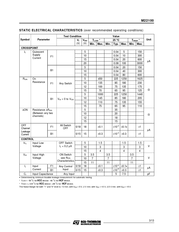
STMicroelectronics M22100
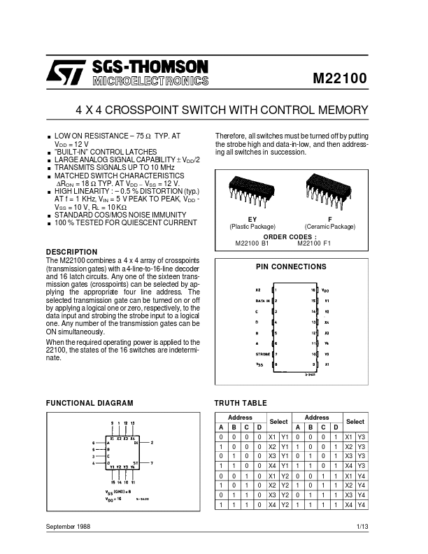
The M22100 combines a 4 x 4 array of crosspoints (transmission gates) with a 4-line-to-16-line decoder and 16 latch circuits. The selected transmission gate can be turned on or off by applying a logical one or zero, respectively, to the data input and strobing the strobe input to a logical one. When the required operating power is applied to the 22100, the states of the 16 switches are indeterminate.| Part No. | M22100 |
|---|---|
| Datasheet | M22100 Download |
| Manufacturer |  STMicroelectronics |
| Description | 4 X 4 CROSSPOINT SWITCH |
| Buy | Stock & Price |
DESCRIPTION
Any one of the sixteen transmission gates (crosspoints) can be selected by applying the appropriate four line address. Any number of the transmission gates can be ON simultaneously. PIN CONNECTIONS FUNCTIONAL DIAGRAM TRUTH TABLE Address A 0 1 0 1 0 1 0 1 B 0 0 1 1 0 0 1 1 C 0 0 0 0 1 1 1 1 D 0 0 0 0 0 0 0 0 X1 Y1 X2 Y1 X3 Y1 X4 Y1 X1 Y2 X2 Y2 X3 Y2 X4 Y2 Select A 0 1 0 1 0 1 0 1 Address B 0 0 1 1 0 0 1 1 C 0 0 0 0 1 1 1 1 D 1 1 1 1 1 1 1 1 X1 Y3 X2 Y3 X3 Y3 X4 Y3 X1 Y4 X2 Y4 X3 Y4 X4 Y4 Select September 1988 1/13 M22100 ABSOLUTE MAXIMUM RATING Symbol VDD * Vi II Ptot Parameter Supply Voltage: Ceramic Types Plastic Types Input Voltage DC Input Current (any one input) Total Power Dissipation (per package) Dissipation per Output Transistor for Top = Full Package Temperature Range Operating Temperature: Ceramic Types Plastic Types Storage Temperature Value -0.5 to +20 -0.5 to +18 -0.5 to VDD + 0.5 ± 10 200 100 -55 to +125 -40 to +85 -65 to +150 Unit V V V mA mW mW o o o Top Tstg C C C Stresses above those listed under ”ABSOLUTE MAXIMUM RATINGS
” may cause permanent damage to the device.