M24M01
M24M01 is 1 Mbit Serial IC Bus EEPROM manufactured by STMicroelectronics.
FEATURES
SUMMARY 2 s 400 k Hz High Speed Two Wire I C Serial Interface s
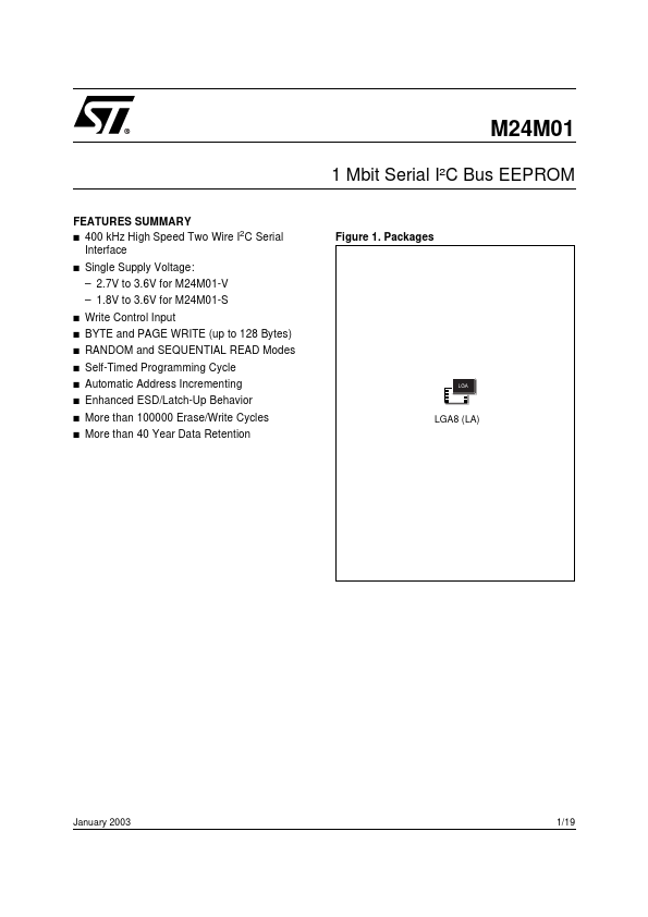
Figure 1. Packages
Single Supply Voltage:
- 2.7V to 3.6V for M24M01-V
- 1.8V to 3.6V for M24M01-S s s s s s s s s
Write Control Input BYTE and PAGE WRITE (up to 128 Bytes) RANDOM and SEQUENTIAL READ Modes Self-Timed Programming Cycle Automatic Address Incrementing Enhanced ESD/Latch-Up Behavior More than 100000 Erase/Write Cycles More than 40 Year Data Retention
LGA8 (LA)
January 2003
1/19
SUMMARY DESCRIPTION
The M24M01 is a 1 Mbit (131,072 x 8) electrically erasable programmable memory (EEPROM) accessed by an I2C-patible bus. Figure 2. Logic Diagram
When writing data to the memory, the device inserts an acknowledge bit during the 9th bit time, following the bus master’s 8-bit transmission. When data is read by the bus master, the bus master acknowledges the receipt of the data byte in the same way. Data transfers are terminated by a Stop condition after an Ack for Write, and after a No Ack for Read. Figure 3. LGA Connections
2 E1-E2 SCL WC M24M01 DU E1 E2 VSS VSS
AI04048B
SDA M24M01 1 2 3 4 8 7 6 5
AI04051C
VCC WC SCL SDA
Table 1. Signal Names
E1, E2 SDA SCL WC VCC VSS Chip Enable Serial Data Serial Clock Write Control Supply Voltage Ground
Note: 1. DU = Don’t Use (should be left unconnected, or tied to VSS)
These devices are patible with the I2C memory protocol. This is a two wire serial interface that uses a bi-directional data bus and serial clock. The devices carry a built-in 4-bit Device Type Identifier code (1010) in accordance with the I2C bus definition. The device behaves as a slave in the I2C protocol, with all memory operations synchronized by the serial clock. Read and Write operations are initiated by a Start condition, generated by the bus master. The Start condition is followed by a Device Select Code and RW bit (as described in Table 2), terminated by an acknowledge bit.
Power On Reset: V CC Lock-Out Write Protect In order to prevent data...