DESCRIPTION
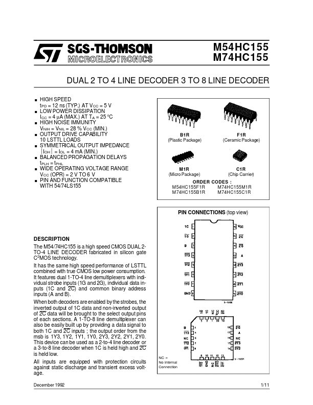
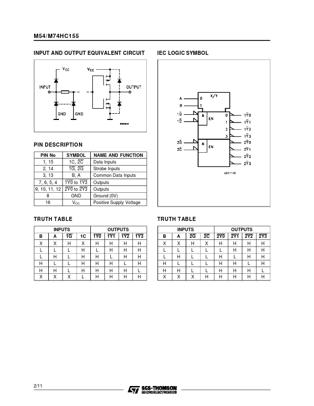
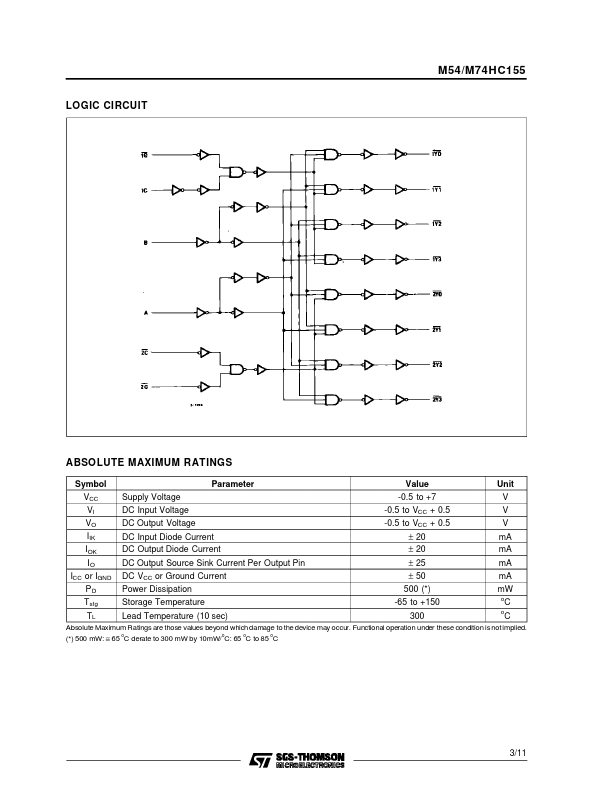
When both decoders are enabled by the strobes, the inverted output of 1C data and non-inverted output of 2C data will be brought to the select output pins of each sections. A 1-TO-8 line demultiplexer can also be easily built up by providing a data signal to both 1C and 2C inputs ; the output order from the msb is 1Y3, 1Y2, 1Y1, 1Y0, 2Y3, 2Y2, 2Y1, 2Y0. This device can be used as a 2-to-4 line decoder or a 3-to-8 line decoder when 1C is held high and 2C is held low. All inputs are equipped with protection circuits against static discharge and transient excess voltage. December 1992 NC = No Internal Connection 1/11 M54/M74HC155 INPUT AND OUTPUT EQUIVALENT CIRCUIT IEC LOGIC SYMBOL PIN DESCRIPTION
PIN No 1, 15 2, 14 3, 13 7, 6, 5, 4 SYMBOL 1C, 2C 1G, 2G B, A 1Y0 to 1Y3 NAME AND FUNCTION Data Inputs Strobe Inputs Common Data Inputs Outputs Outputs Ground (0V) Positive Supply Voltage 9, 10, 11, 12 2Y0 to 2Y3 8 GND 16 VCC TRUTH TABLE B X L L H H X INPUTS A 1G X L H L H X H L L L... STMicroelectronics