DESCRIPTION
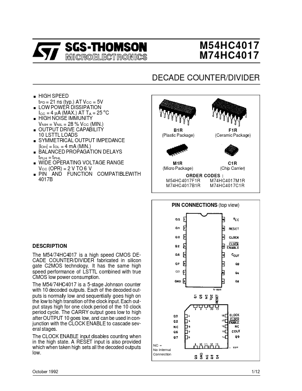
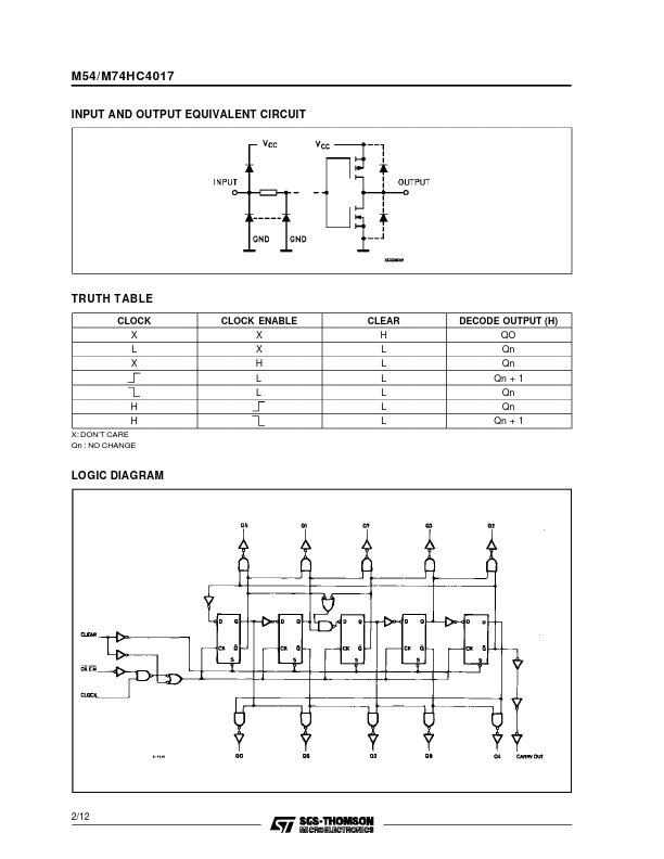
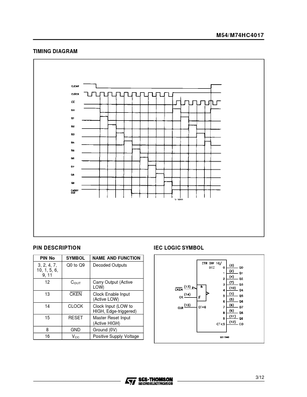
Each of the decoded outputs is normally low and sequentially goes high on the low to high transition of the clock input. Each output stays high for one clock period of the 10 clock period cycle. The CARRY output goes low to high after OUTPUT 10 goes low, and can be used in conjunction with the CLOCK ENABLE to cascade several stages. The CLOCK ENABLE input disables counting when in the high state. A RESET input is also provided which when taken high sets all the decoded outputs low. NC = No Internal Connection Q3 October 1992 1/12 M54/M74HC4017 INPUT AND OUTPUT EQUIVALENT CIRCUIT TRUTH TABLE CLOCK X L X CLOCK ENABLE X X H L L H H X: DON’T CARE Qn : NO CHANGE CLEAR H L L L L L L DECODE OUTPUT (H) QO Qn Qn Qn + 1 Qn Qn Qn + 1 LOGIC DIAGRAM 2/12 M54/ M74HC4017 TIMING DIAGRAM PIN DESCRIPTION
PIN No 3, 2, 4, 7, 10, 1, 5, 6, 9, 11 12 13 14 15 8 16 SYMBOL Q0 to Q9 NAME AND FUNCTION Decoded Outputs IEC LOGIC SYMBOL COUT CKEN CLOCK RESET GND V CC Carry Output (Active LOW) Clock Enabl... STMicroelectronics