DESCRIPTION
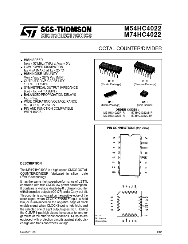
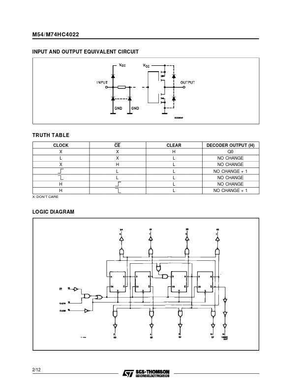
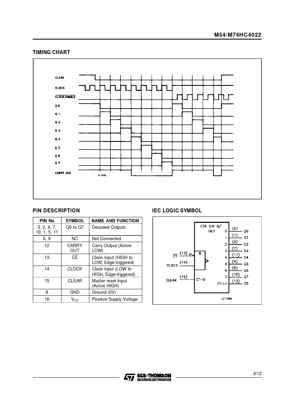
This counter is advanced on the positive edge of the clock signal when CLOCK ENABLE input is held low, or is advanced on the negative edge of clock enable signal when CLOCK input is held high, and the selected one of eight outputs goes high. Holding the CLEAR input high clears the counter to zero regardless of the other input conditions. All inputs are equipped with protection circuits against static discharge and transient excess voltage. October 1992 NC = No Internal Connection 1/12 M54/M74HC4022 INPUT AND OUTPUT EQUIVALENT CIRCUIT TRUTH TABLE CLOCK X L X CE X X H L L H H X: DON’T CARE CLEAR H L L L L L L DECODER OUTPUT (H) Q0 NO CHANGE NO CHANGE NO CHANGE + 1 NO CHANGE NO CHANGE NO CHANGE + 1 LOGIC DIAGRAM 2/12 M54/ M74HC4022 TIMING CHART PIN DESCRIPTION
PIN No 3, 2, 4, 7, 10, 1, 5, 11 6, 9 12 13 14 15 8 16 SYMBOL Q0 to Q7 NC CARRY OUT CE CLOCK CLEAR GND V CC NAME AND FUNCTION Decoded Outputs Not Connected Carry Output (Active LOW) Clock Input (HIGH to LOW, Edge-triggere... STMicroelectronics