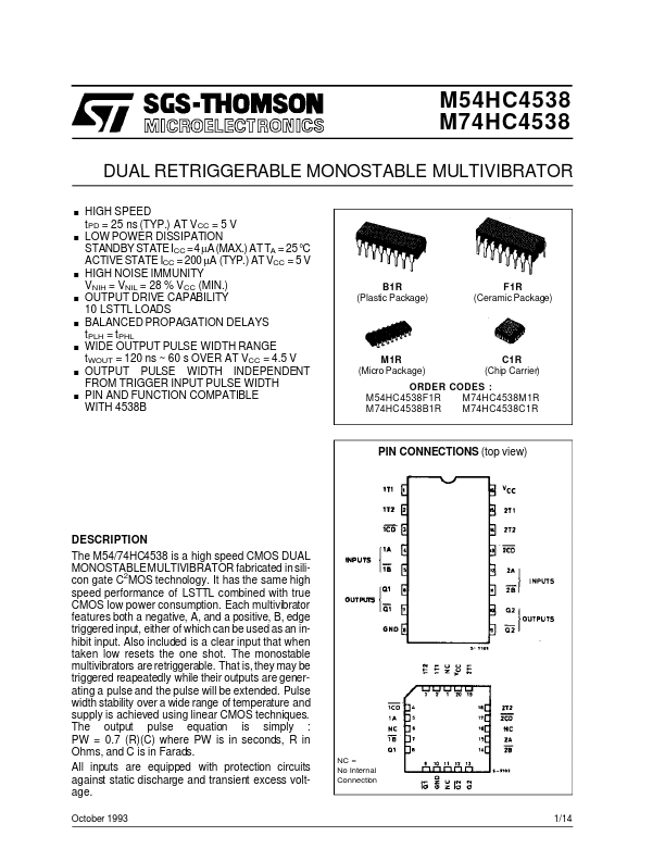
DESCRIPTION
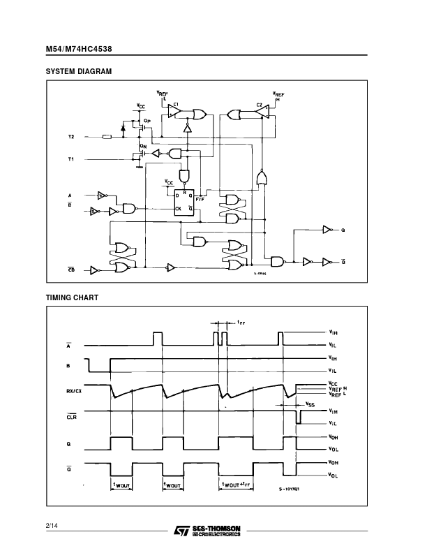
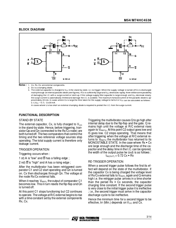
Also included is a clear input that when taken low resets the one shot. The monostable multivibrators are retriggerable. That is, they may be triggered reapeatedly while their outputs are generating a pulse and the pulse will be extended. Pulse width stability over a wide range of temperature and supply is achieved using linear CMOS techniques. The output pulse equation is simply : PW = 0.7 (R)(C) where PW is in seconds, R in Ohms, and C is in Farads. All inputs are equipped with protection circuits against static discharge and transient excess voltage. October 1993 NC = No Internal Connection 1/14 M54/M74HC4538 SYSTEM DIAGRAM TIMING CHART 2/14 M54/ M74HC4538 BLOCK DIAGRAM Notes : 1. Cx, Rx, Dx are external components. 2. Dx is a clamping diode. 3. The external capacitor is charged to VCC in the stand-by state, i.e. no trigger. When the supply voltage is turned off Cx is discharged mainlythrough an internal parasitic diode (see figures). IfCx is sufficiently largeand VCC decreases rapidy, there willbesome possibility of damaging the I.C. with a surge current or latch-up. STMicroelectronics