DESCRIPTION
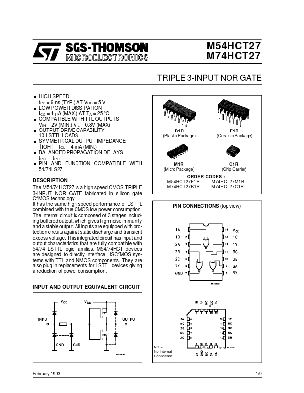
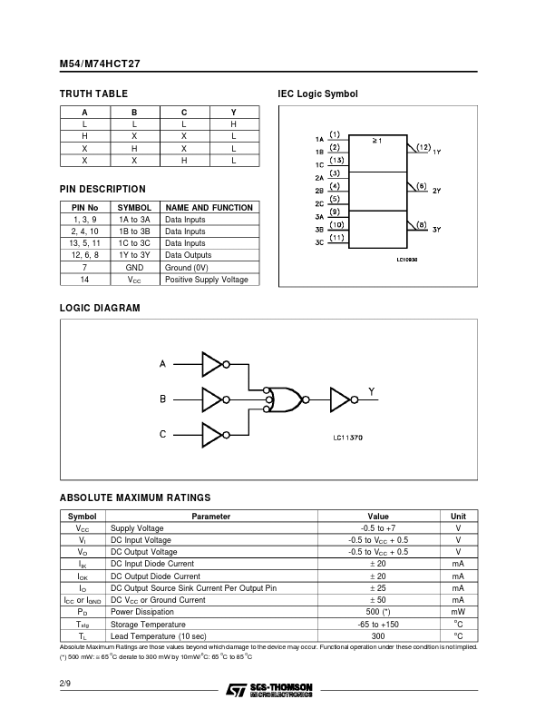
All inputs are equipped with protection circuits against static discharge and transient excess voltage. This integrated circuit has input and output characteristics that are fully compatible with 54/74 LSTTL logic families. M54/74HCT devices are designed to directly interface HSC2MOS systems with TTL and NMOS components. They are also plug in replacements for LSTTL devices giving a reduction of power consumption. INPUT AND OUTPUT EQUIVALENT CIRCUIT ORDER CODES : M54HCT27F1R M74HCT27M1R M74HCT27B1R M74HCT27C1R PIN CONNECTIONS (top view) NC = No Internal Connection February 1993 1/9 M54/M74HCT27 TRUTH TABLE A L H X X B L X H X C L X X H Y H L L L IEC Logic Symbol PIN DESCRIPTION
PIN No 1, 3, 9 2, 4, 10 13, 5, 11 12, 6, 8 7 14 SYMBOL 1A to 3A 1B to 3B 1C to 3C 1Y to 3Y GND VCC NAME AND FUNCTION Data Inputs Data Inputs Data Inputs Data Outputs Ground (0V) Positive Supply Voltage LOGIC DIAGRAM ABSOLUTE MAXIMUM RATINGS
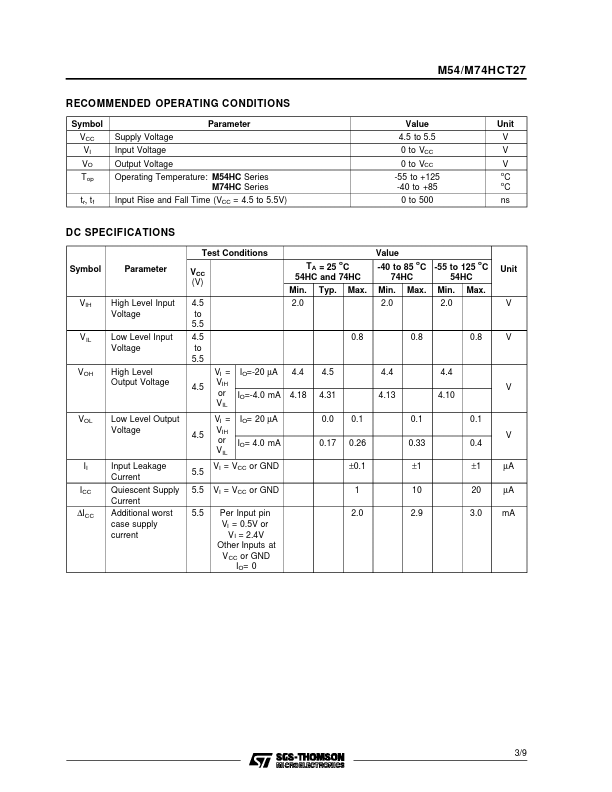
Symbol VCC VI VO IIK IOK ICC IO or IGND PD Tstg TL Supply Vol... STMicroelectronics