DESCRIPTION
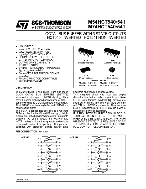
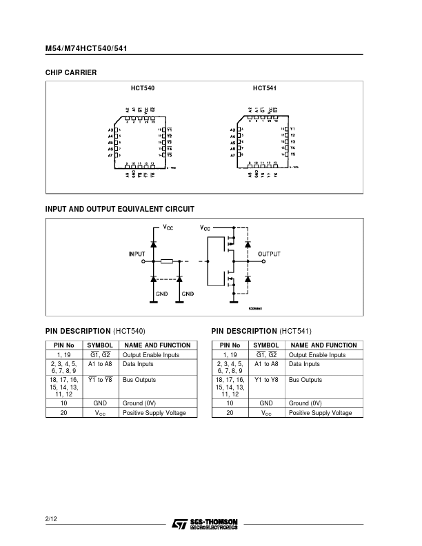
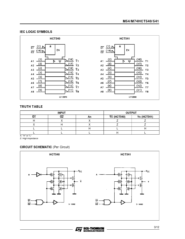
The 3 STATE control gate operates as a two input AND such that if either G1 and G2 are high, all eight outputs are in the high impedance state. In order to enhance PC board layout, the HCT540 and HCT541 offers a pinout having inputs and outputs on opposite sides of the package. All inputs are equipped with protection circuits against static PIN CONNECTION (top view) HCT540 HCT541 discharge and transient excess voltage. This integrated circuit has input and output characteristics that are fully compatible with 54/74 LSTTL logic families. M54/74HCT devices are designed to directly interface HSC2MOS systems with TTL and NMOS components. They are also plug in replacements for LSTTL devices giving a reduction of power consumption. IT IS PROHIBITED TO APPLY A SIGNAL TO BUS TERMINAL WHEN IT IS IN OUTPUT MODE. WHEN A BUS TERMINAL IS FLOATING (HIGH IMPEDANCE STATE) IT IS REQUESTED TO FIX THE INPUT LEVEL BY MEANS OF EXTERNAL PULL DOWN OR PULL UP RESISTOR. October 1993 1/12 M54/M74HCT... STMicroelectronics